Lab 2, More Spice and the Compensated Probe
Outcome
of this lab:
Be
more familiar with Spice. Understand
the mechanism of the compensated scope probes.
Instructions:
1. Time delay of pulses.
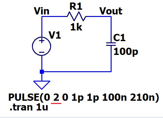
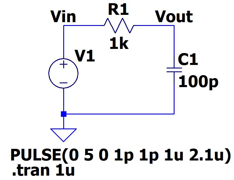
1.1 Build the following circuit in LTSpice using symbols (not Spice Code). Run the simulation and explain the results. (10 points)

1.2 Make the following changes to the
circuit and tell if you can charge up the 100 p capacitor to the full
voltage range, explain why and why not?
a. Reduce the voltage supply's Von to 2 V, keep all other parameters unchanged. (10 points)
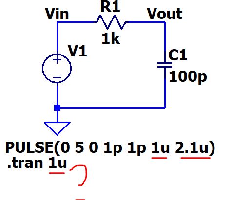
b. Change Von back to 5V, Change the Ton and Tperiod to 1u and 2.1u
separately. (you may need to increase your simulation time to show more
pulse periods). (10 points)
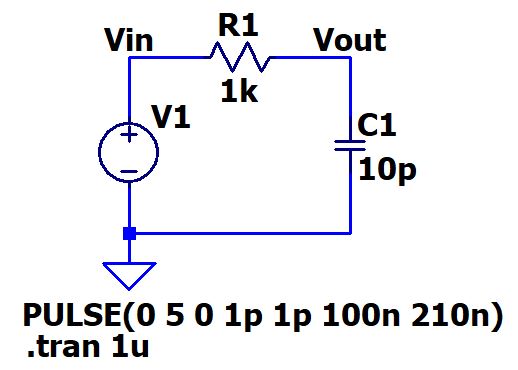
c. Change all the parameters back to the original ones in the figure in
Section 1.1. Replace the 100p with a 10p capacitor. Simulate it and
explain the results. (10 points)
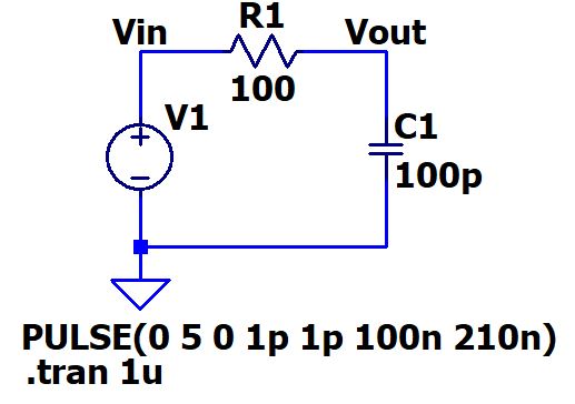
d. Change
all the parameters back to the original ones in the figure in Section
1.1. Replace the 1k resistor with a 100 ohm resistor. Simulate it and
explain the results. (10 points)
1.3 Build the following circuit on your breadboard, use the function
generator to generate the square wave, use the oscilloscope to probe
the signal. Adjust the frequency of the square wave on your function
generator to keep your capacitor fully charged to the full voltage
range. Meaure the time delay use the oscilloscope (Cursors). Use your thumb drive
to save the input/output waves on the oscilloscope. (if you do not have
a thumb drive, take a picture use your phone). (10 points)
2. Time delay and amplitude attenuation of sinewaves.
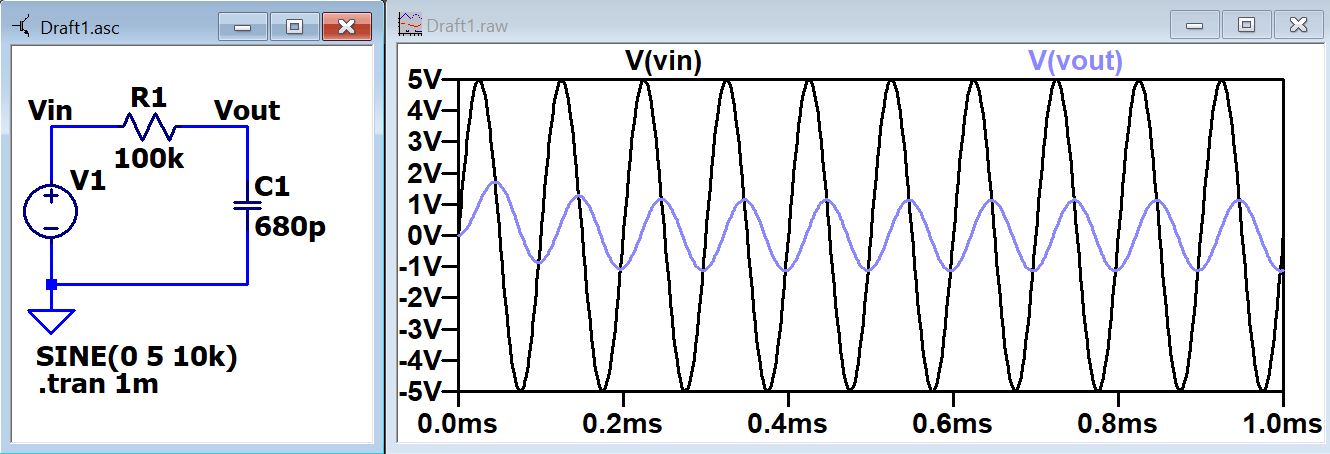
2.1 Build the following circuit in
LTSpice AND on the breadboard. Calculate, simulate, and measure the
time delay and Vo/Vi of this circuit. Compare the results in a table. (10 points)
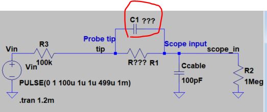
3. The Compensated Probe
The circuit model of the oscilloscope probe you used in the lab:
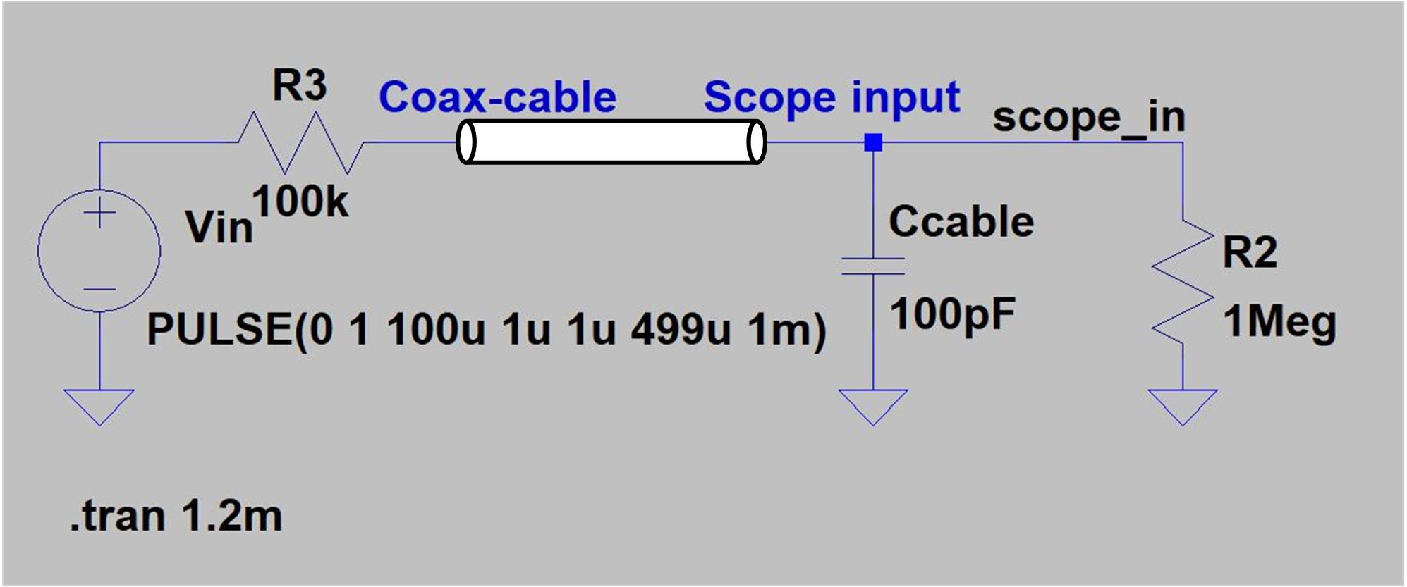
The cable has a parasitic capacitance, the value is around 100 pF,
which will always be there, won't disapear. The equivalent capacitance
is drawn in the circuit above.
The input resistance of the oscilloscope is 1 MEG ohm, also, the 1 MEG
ohm resistor is connected to the circuit in this model.
The 100 pF capacitance slows down the probe, which means if you have a
high speed input, the probe will introduce an extra delay to the
circuit.
If we attenuate the amplitude of the input by 10 times, and then
're-plot' the curve in the oscilloscope by 10 times high, the output
showing on the oscilloscope will stay the same but the actuall input
is 10 times smaller. This will relieve the driving load and make the
circuit faster.
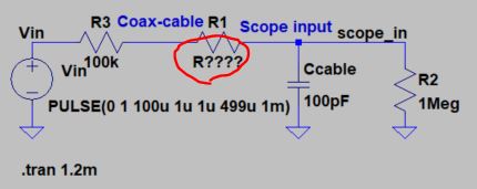
3.1 Let's attenuate the DC voltage first. Build the following circuit in
LTSpice, design the unknown resistor value, to make Vo/Vi=1/10, in DC. Report
the simulation result. Show why you pick up that resistor value. (10 points)
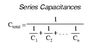
3.2 Now let's take care of the AC component. Build the following
circuit and design the capacitance value. Report
the simulation result. Show why you pick up that capacitor value. (10 points)
(The large resistors perform as AC blockers in the circuit).
Hint:
3.3 Comment
on where the type of scope probe (i.e., 1:1, 10:1, 100:1, etc.) is set
on your scope (some scopes detect the type of probe used automatically). Change it to 1:1, show/discuss what will happen on the scope (Use the same signal input in section 3.2). (10 points)
--------------------
The end of the lab