The
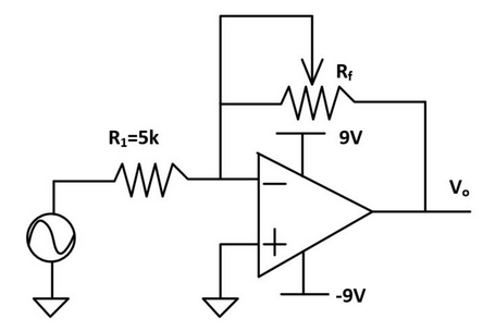
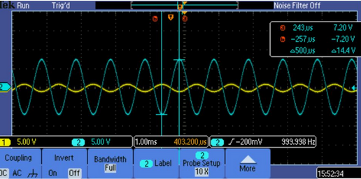
circuit show in figure 1 is build on a bread board and is tested
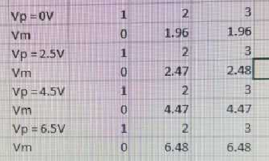
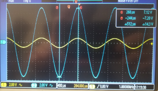
(figure 1,2). The circuit shown in figure 3 is built. The op amp is
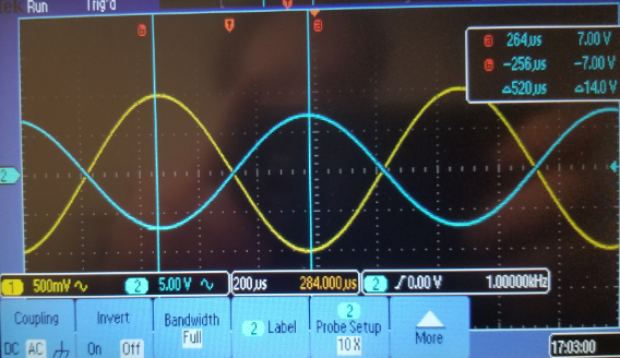
powered up by +9V and -9V with Vin = sinewave (1k Hz, 2V Vpp). As Vout
and Vin is probed, the potentiometer is adjusted to find the max
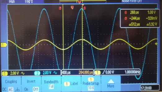
amplification while still maintaining data resolution (figure 4). The
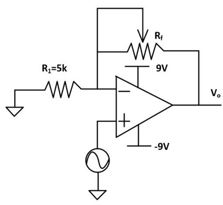
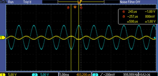
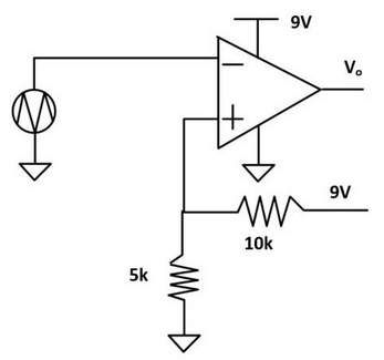
second configuration shown in figure 5 is built and tested using the
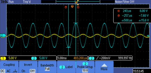
same Vin as the previous configuration (figure 5,6). The circuit shown
in figure 7 was built and tested with a 100ohm resistor (figure 7,8).
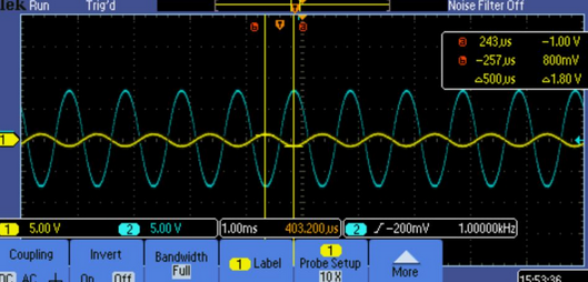
The same circuit from task 4.1 is used, but the 100ohm resistor is
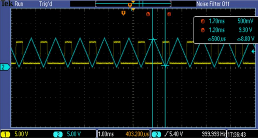
replaced with a 1mega ohm resistor (figure 9,10). The circuit shown in
figure 11 (comparitor) is built and tested (figure 11, 12)
|
LM741
OP AMP
5k resistor
100k Potentiometer
|
x1
x1
x1
|