| Introduction: |
| This lab required the design of a PCB (printed circuit board) to continue the line following car project. PCB versions of project circuits can add professionalism to even simple circuits. This lab follows the design and ordering of a PCB circuit. |
| Methods: | Materials: | |
| Tutorials
were
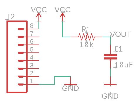
followed in order to learn how to use Eagle PCB. First, a schematic of
a simple capacitor-resistor circuit was designed (figure 1). The
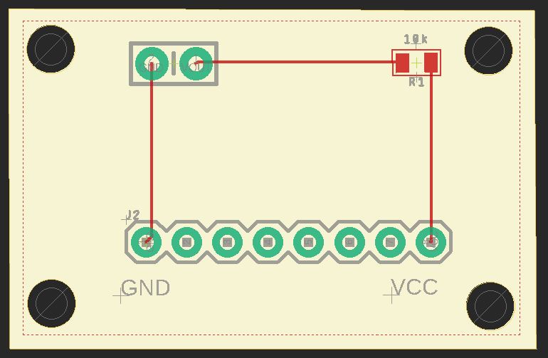
schematic was then transfered to a board (figure 2). The Gerber files
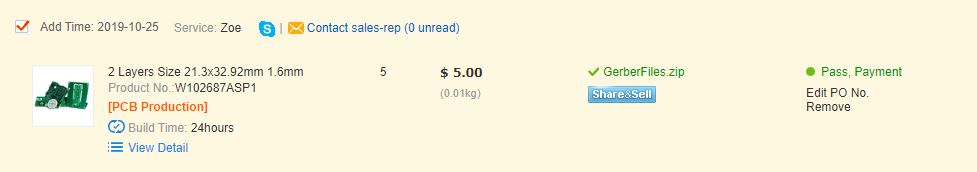
were generated an uploaded to pcbway.com and the files were
confirmed(figure 3). The tutorials then showed the process for creating
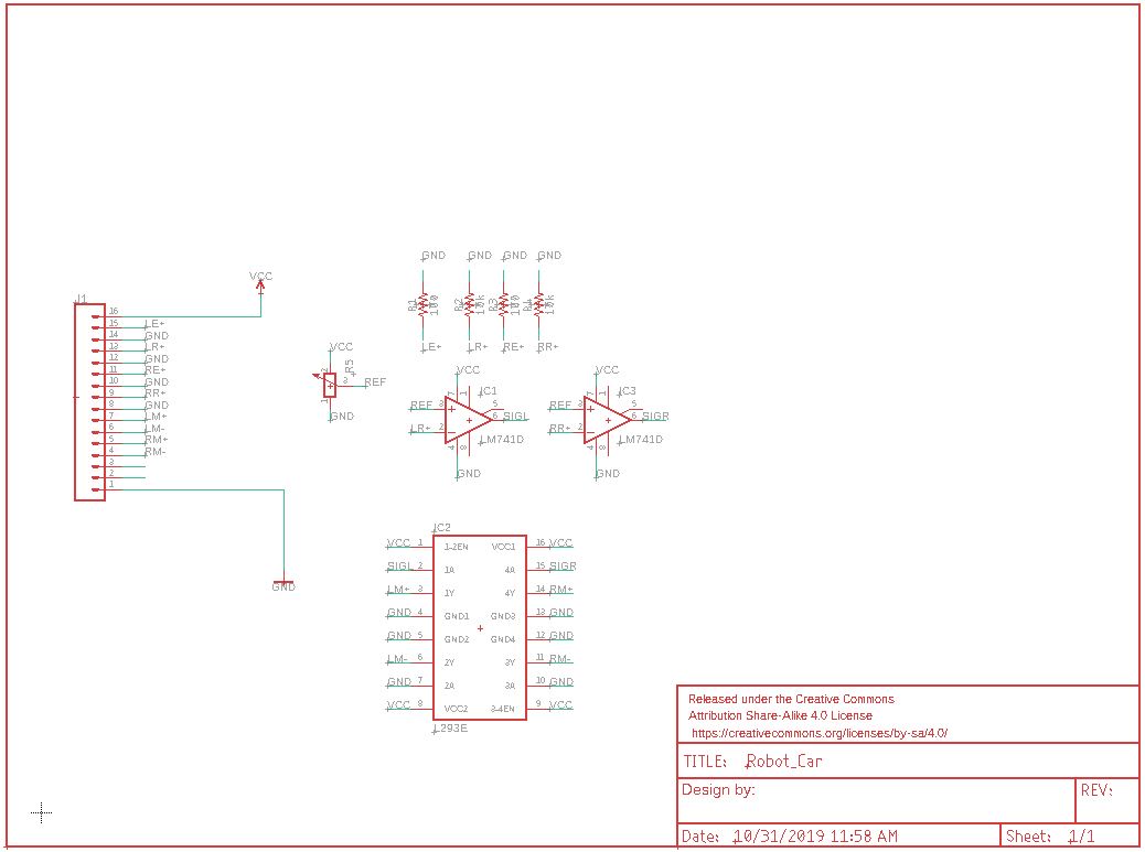
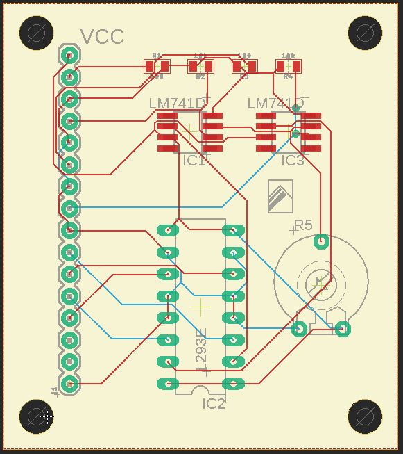
new components. The schematic for the line following car wad then
created and transfered to a board (figure4, 5). The line following car
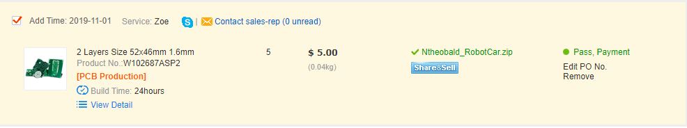
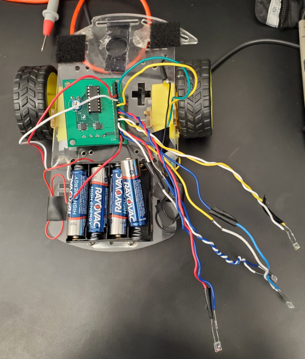
gerber files were uploaded and confirmed by pcbway (figure 6). The car
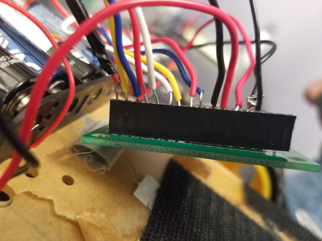
was built and tested but was found to have major design flaws that kept
it from working at all (figure 7). |
Eagle
PCB
|
x1 |
| Figure
1: Capacitor-Resistor Circuit Schematic |
Figure
2: Capacitor-Resistor Circuit Board |
|
|
| Figure 3:
Capacitor-Resistor Confirmation |
 |
| Figure 4: Line Following Car Schematic |
Figure 5: Line Following Car Board |
 |
 |
| Figure 6: Line Following Car Confirmation |
 |
| Figure 7: Line Following Car Testing |
   |