
| Introduction: |
| The Lab required the design of a DC motor driving Circuit. Th circuit took information about its environment and used it to navigate a small car through a black loop path on the surface of a table. The motor driving circuit consted of one NE Package 16-Pin PDIP motor driver. Th driver recieved an on or off signal via a dual comparator circuit. The dual comparator circuit used two comparators to determine whether the left or right IR recievers recieved light from two IR LEDs (that were parallel to the left and right IR recievers). The comparator circuit maintained the connection between pins 2A and 3A to ground, allowing the motors to run, until either IR recievers no longer recieved light from their respective IR LED. When connection between the IR reciever and its respective IR LED was broken, the power to the motor on the same side of the car would be dcontinued. |
| Methods: | Materials: | |
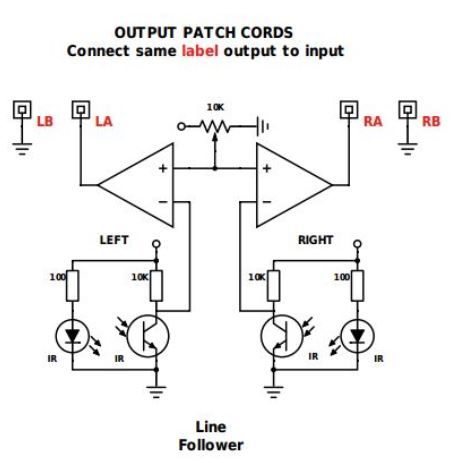
| The circuit shown in figure
1 and figure 2 was built on a small prototyping bread board (figure1,
2). Wires LA and RA were connected to pins 2A and 3A respectivly. Wires
LB and RB and pins 1A and 4A were grounded. The breadboard was then
attatched to a car body and the motors were connected to their
respective pins on the DC motor driver. The IR Reciever was situated
near the center front of the car where it can point at the table
surface. The IR LED was situated closely to the reciever but on the
outside of the car where it can shine on the table and be reflected at
the reciever. Another IR reciever/LED assembly was mirrored in parallel
on the opposite side of the car. Power was provided to the car and it
successfully made a loop around the table. |
NE Package 16-Pin PDIP
Car Body 5v Power Supply 100-ohm resistor 10k resistor IR LED IR Receiver | x1 x1 x1 x2 x2 x2 x2 |
| Figure
1: Comparator circuit diagram |
Figure
2: DC motor driver circuit diagram |
|
|
| Figure 3: Testing the car |
|
|
| No notes were taken during the course of this lab. |