ENGR201 Lab 2019 Fall
Lab 3
Name: Nic Theobald
Email: nstheobald@fortlewis.edu

Pushbuttons, Leds, and DC Motors

Introduction: DC Motor ICs are used to control DC motors with different kinds of input methods. An OP AMP with photo resistor and push buttons are examples of inputs used to control the DC motors.
Materials:      
Power supply 
Multimeter
1k resistors
10k resistors
LED
Push Button
NE Package 16 pin PDIP
Photoresistor
DC Motor
741 OP AMP
x1
x1
x2
x1
x1
x2
x1
x1
x2
x1
     

Methods:

The LED and button circuit shown in figure 1 was constructed and proven to cause the LED to turn off when the button is compressed (figure 1 and 2). The circuit shown in figure 3 was built on the breadboard and the pushbuttons are used to turn the motor on and off (figure 3). Two push buttons are then added to the circuit from figure 3 (figure 4). Three different voltages (6V, 9V, and 12V) are then run through the same circuit via pin 8 (figure 5).  The circuit shown in figure F6, similar to the circuit in figure F3 but with a photoresistor and op amp, is build and tested (figure 6). When a box is placed over the circuit the motors are allowed to run when the push buttons are compressed (figure 7).

4. Results:

Task 1:

Normally On and Normally Off LED Circuits:
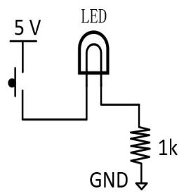
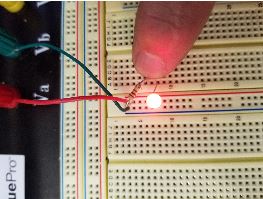
F1 Normally off LED circuit

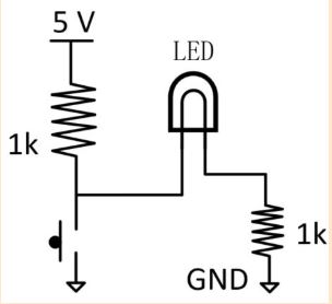
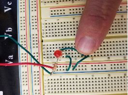
F2 Normally on LED circuit


Task 2:

Controling DC Motors Using DC Motor Driver and Pushbuttons:
F3 Motor driving circuit


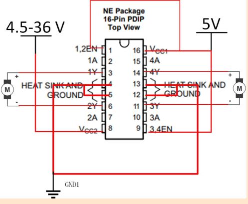
F4 Motor driving circuit with two push buttons

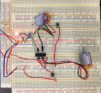
F5 Circuit with 6V, 9V, and 12V run through pin 8


Task 3:

Motor Driving Circuit With Photoresistor
F6 Motor driving circuit with push button and photoresistor. Photoresistor input is handled by an OP AMP

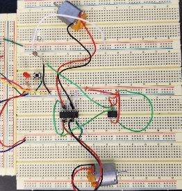
F7 Video of fan spinning when photoresistor is covered by box

5. Discussion: No Notes were Taken During This Lab