ENGR201 Lab 2019 Fall
Lab 2
Name: Nic Theobald
Email: nstheobald@fortlewis.edu

Circuit Simulation Lab

Introduction: Circuit Simulation is a usefull tool for checking your work. In this lab, we built multiple circuits and then simulated them in LTSPICE.
Materials:
    Items Used:
        -Power Supply and Cables
        -Multimeter and Cables
        -Resistors: 1k, 2k, 3k, 10k
        -Breadboard
Methods:

Three 
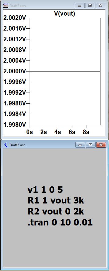
different methods were used to build the circuit in LTSPICE. The methods required us to write the spice code in an external .txt file, write the code in the '.op' option, and use electrical symbols in the 
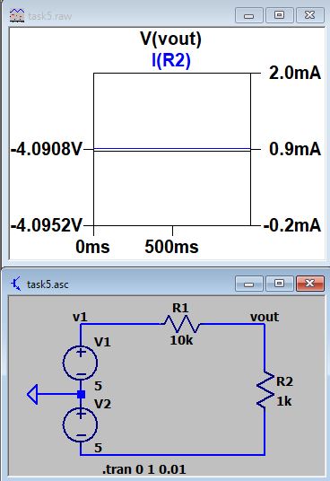
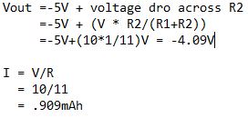
library directly (Figure 1,2,3). We then calculated the current, I, and 
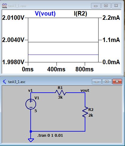
voltage, Vout, using 'Ohm's Law.' We then verified our calculations using both simualtion and multimeter measurement on a breadboard 
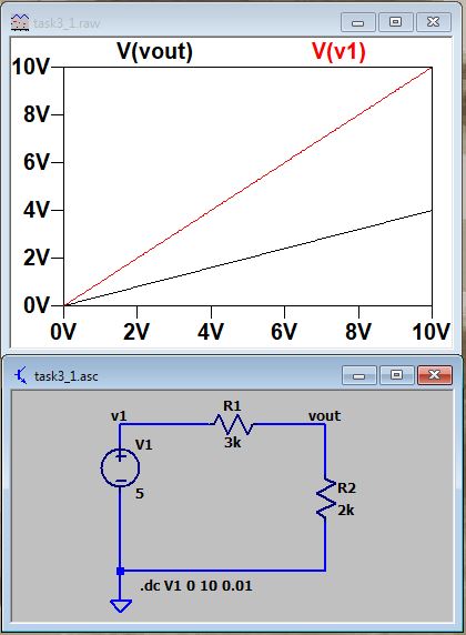
(Figure 4,5). A DC Sweep calculation for V1 
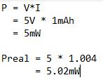
is run from 0 V stops at 10 V (Figure 6). The theoretical and real life power consumption of the ciruit were calculated using P=V*I (Figure 7). Multimeter and simulation are used verify our calculations of current and Vout on the circuit in figure 9 (Figure 8, 9).
 

4. Results:

Task 1:

Different Methods of Building Circuits in LTSPICE:
F1 Power supply 5v while connected to breadboard

F2 Build using '.op' option

F3 Build using electrical symbols in the library directly


Task 2:

Current and Voltage Calculations Using Simulation and Multimeter.
F4 Simulated Current and Voltage
           (Kompozer error causing Voltage to not be shown in image).


F5 Multimeter Calculations and Hand Calculations


Task 3:

DC Sweep Simulation for V1 (0V to 10 V)
F6 Vout and V1 during DC sweep simulation (0V to 10V).


Task 4:

Theoretical and Real Life Power Consumption Calculation.
F7 Real life, and theoretical power consumption:


Task 5:

Current and Voltage Calculation of  Positive-Negative Power Supply
                               F8 Theoretical power consumption:                             
F9 Multimeter measurements of current aqnd Vout


5. Discussion: K
ompozer error causing Voltage to not be shown in figure 4. Image viewer on computer clearly shows the line representing voltage, but kompozer seems to filter out some details.