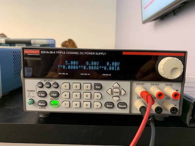
| F2 Power supply 5v while connected to breadboard |
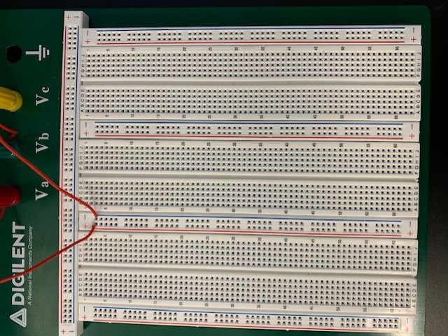
F1 Bread Board while connected to 5v power supply |
F4 Power supply 5.2v while connected to breadboard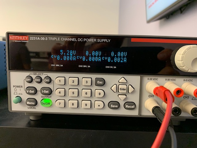 |
F3 Bread Board while connected to 5.2v power supply |
F5 Multimeter while connected to 5v power supply |
F7 Multimeter while connected to bread board with resistors | F6 Bread Board with resistors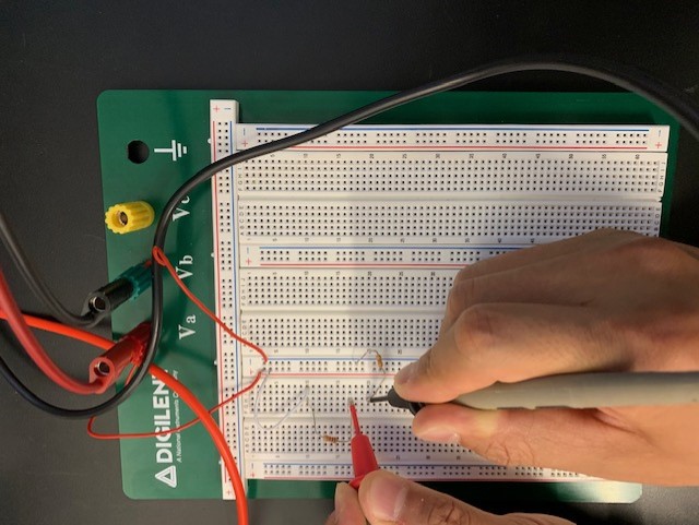 |
|
Table 1:
|
F8 Osciliscope while connected to breadboard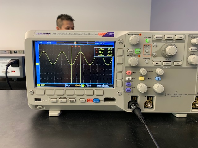 |