ENGR201 Fall 2019
Lab 6&8 PCB design and Line Follower
Name: Jesse Duran Email: Jiduran@fortlewis.edu
1. PCB design and Line Follower
2. The goal of these labs was to be able to design a PCB using Eagle
software of our robot car as well be able to create user defined
componant libraries. The soldering skills as well as robot car knowlege
was applied to the final goal of the robot car following a line.
3. Materials:
2x 100 ohm smt resistors
2x 10k ohm smt resistors
10k potentiometer
2x 741 smt Op Amps
Robot car
Line follower PCB
Soldering kit
Methods:
First four Eagle tutorials were completed, from designing a schematic
to a user defined library. Next our Line Follower circuit was created
using Eagle and submitted for manufacture from PCBway.com. Finally the
componants were soldered onto the PCB and it was tested by mounting it
on the robot car and repeating the line test.
4. Results:
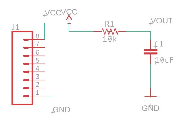
Figure 1. Board schematic of PCB tutorial
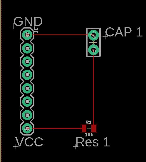
Figure 2. Board layout of PCB tutorial
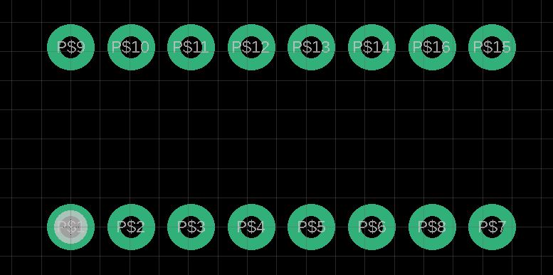
Figure 3. Created user library componant
Figure 4. Line Follower schematic
Figure 5. Line Follower board layout
Figure 6. Componants soldered on PCB
Video 1. PCB mounted on robot car following line
5. Discussion:
This lab tied in the skill we have been learning all semster into a
single project. The benchtop equipment was used to test the circuit on
the board to ensure a proper solder job. Going forwad knowing how to design a PCB will be a valuable skill in the tool belt.