ENGR337 Lab 2019 Fall
Lab 3
Pushbuttons, LEDs, and DC Motors
Name: Jesse Duran
Email: Jiduran@fortlewis.edu

Pushbuttons, LEDs, and DC Motors


2. The objective of this lab was to gain familiarity with using pushbuttons to control a circut, LEDs and a DC motor. The DC motors were controled with pushbuttons and by a photo resistor.These skills will later be incorperated into our robot cars.
Materials
1k ohm resistor
10k ohm resistor
Power Supply
Bread board
Jumper wires
LED
2x DC motors
L293D chip
Mulitmeter
Pushbuttons
CdS photoresistor
741 amplifier chip

Methods:
First a circut was built that turned on an LED with a push button, figure 1. This circut was then modified to turn off the LED when the pushbutton was pressed, figure 2. The DC motors were then connected and tested at differnt voltages. Next the DC motors were connected using a L293D controller, two pushbuttons were then added to turn the motors on and off, figure 3. Next a photoresistor and 741 amplifier chip were connected to control when the motor ran (video 2).

4. Results

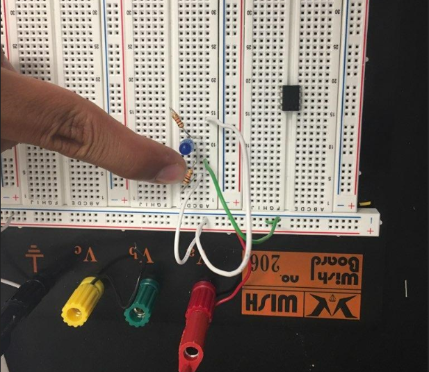
Figure 1. LED being turned on by a pushbutton (task 1.1).


Figure 2. LED being shorted to ground upon pushbutton press.

Figure 3. Two motors with fan attachements connected to breadboard and pushbuttons.


Video 1. Motors controlled with pushbuttons


Video 2. Motors controlled with photo resistor
5. Discussion
The circut trouble shooting in this lab emphesised the need to follow theh circut schematic closely. Later builds of the circut were affected by shorting the power to a common voltage rather than a parallel one. Covering the photoresitor with a box didn't show the results expected, so a hand was used instead.