ENGR201 Lab 2019 Fall
Lab 2 Using LTSpice for circut simulation
Name: Jesse Duran
Email: JIDuran@fortlewis.edu
Lab 2:Using LTSpice for circut simulation
2. Introduction:
Simulation software is a tool that should be in every engineer's
arsenal. This lab is aimed at becoming proficient with LTSpice, a
powerful
circut simulation program, aswell as gaining hands on experince with
electronic testing equipment. The circuts were compared to hand
calculations to ensure each simulation's output was as expected.
3. Materials and Methods
Equipment
|
Breadboard
|
Multimeter
|
DC power supply
|
Jumper wires
|
LTSpice
|
3k Ohm resistors
|
A circut was created in LTSpice using three seperate methods, coding in
Notepad, coding in LTSpice, and using LTSpice's GUI. The same circut
was built on the bread board. The muiltimeter was used to compare the
physical circut to the simulation and hand calcuations.
4. Results:
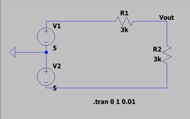
Figure 1. Circut built in LTspice

Figure 2. Circut coded in Notepad

Figure 3. Circut coded in LTSpice
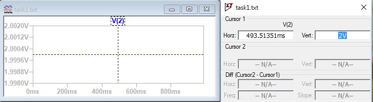
Figure 4. Voltage reading of node V2 (Vout).
|
Calculation
|
Simulation |
Measurment
|
Current
|
0.82 mA
|
1mA
|
0.82mA
|
Vout
|
2.5V
|
2.5V
|
2.5V
|
Table 1. Table of calculated, simulated, and measured Vout and Current.
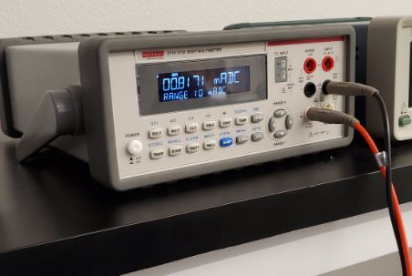
Figure 5. Current reading using multimeter.
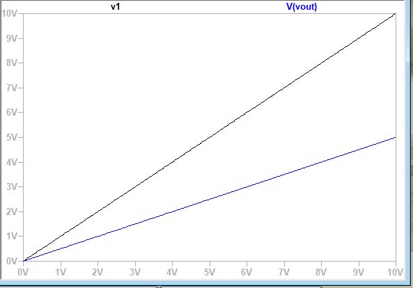
Figure 6. DC sweep of V1 and Vout.
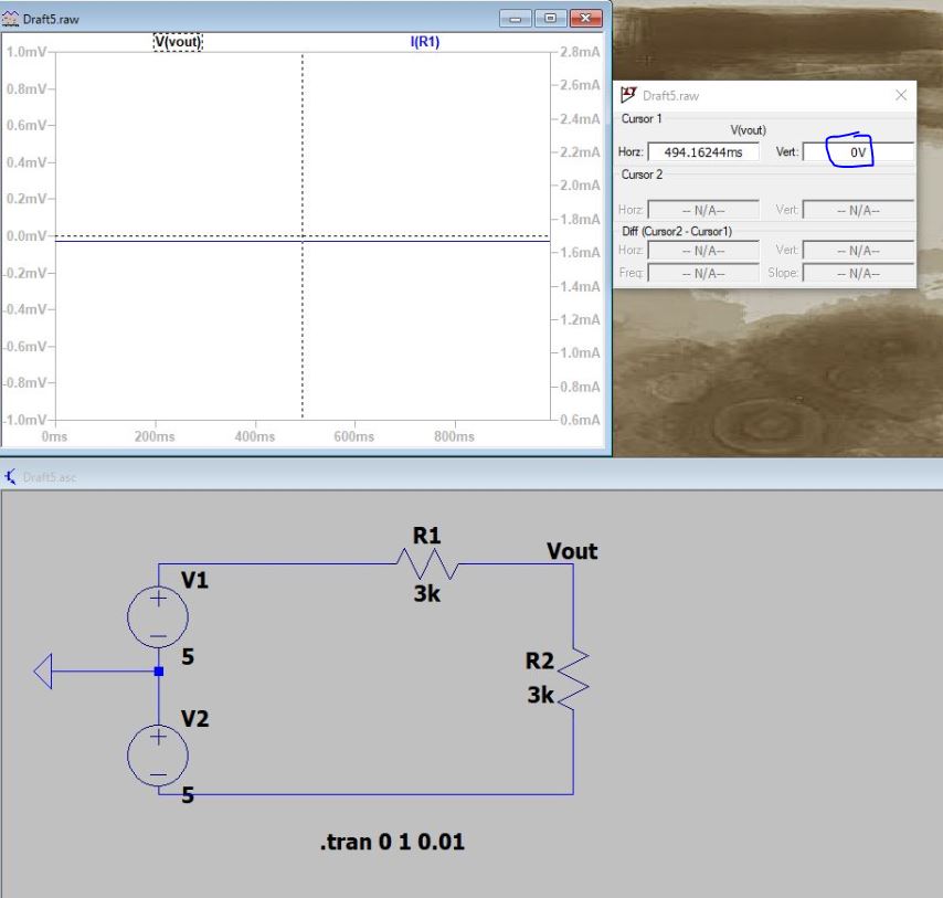
Figure 7. Vout reading 0 volts.
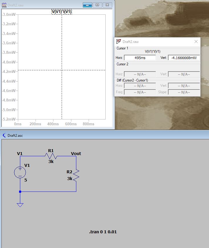
Figure 8. Power consumption reading of circut.
5. Discussion:
Learning how to use LTSpice is a useful skill for evaluating electric
circuts. The different graphs displayed in this lab show the
capabilities of LTSpice. An important factor of testing the circuts by
hand is the comparison it provides to ensure the readings are not
outlandish. The use of the multimeter briges the theoretical and the
reality as well as reenforces the purpose of the equipment.