Lab
4 Soldering
Outcome
of this lab
1.
Understand how IR emitters and receivers work.
2. Practice soldering,
1. Instruction for soldering
Task 1: Read the following instruction and prepare for your soldering work.
1.1. Before soldering
a.
Ensure adequate ventilation. If multiple people are soldering in a
concentrated area, set up a fan to gently blow fumes and vapors away
from you and your co-workers.
b. Keep area clean around
workplace at all times.
1.2. Tools
a. Temperature-controlled
soldering iron with fine tip (about 1/16" to 1/8" wide).
b. Rosin core solder with a
diameter of about 0.032" and a tin-lead (Sn-Pb) content of about
60/40%.
c. A damp (not dry!) sponge
for keeping the tip of the soldering iron clean.
1.3. Soldering
a. Parts to be soldered must
be clean. Test the cleanness by pre-tinning wires before soldering them
together.
b. Whenever possible, fix the
parts to be soldered so that they are not moving during and shortly
after soldering.
c.
Make sure the tip of the soldering iron is clean! An oxidized tip will
not transfer enough heat for the solder to melt fast, but enough to
melt plastic and damage printed circuit boards.
d. Apply a small
amount of fresh solder to the tip of the soldering iron. Then heat the
parts to be soldered and apply solder to the parts (not the iron!)
until it melts. Do not move the parts until the solder has cooled down!
e. A good solder joint looks
shiny and bright silverish. Do not apply excessive amounts of solder!
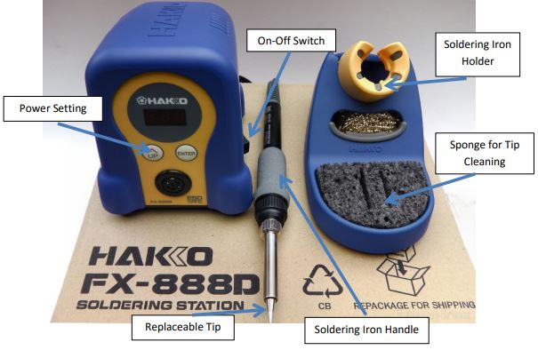
An
example of a soldering station I used in my graduate school, and my lab
at FLC. You may have a slightly different soldering iron, but just show
you the components of a typical soldering station.
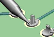
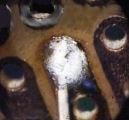
Minimal
thermal linkage due to insufficient solder between the pad and
soldering iron tip. A solder bridge provides thermal linkage to
transfer heat into the pad and component lead.
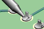
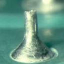
Solder blends to the soldered
surface, forming a small contact angle.
A good solder joint is shown
below.
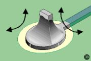
Cold Solder Joints Joints
that are dull or convex are potentially “cold” solder joints. Cold
solder joints DO NOT make a good electrical or
mechanical connection.
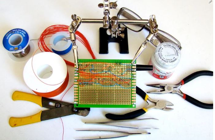
A
complete set of tools you will need for soldering (not including the
iron)
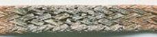
1.4. Use of Solder Wick
a. Solder wick is typically a
ribbon of braided fine copper wire with rosin core flux impregnated
into it.
b. To use solder wick, lay
the wick over the joint to be de-soldered.
c. Apply the heated tip of
the soldering iron to allow the wick to be heated and melt the solder
in the joint.
d. The solder will flow out
of the joint and into the wick through capillary action.
2. Build a light sensing circuit on a prototype PCB board
A photoresistor (or
light-dependent resistor, LDR, or photo-conductive cell) is a
light-controlled variable resistor. The resistance of a photoresistor
decreases with increasing incident light intensity; in other words, it
exhibits photoconductivity. A photoresistor can be applied in
light-sensitive detector circuits, and light-activated and
dark-activated switching circuits.
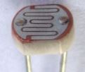
An LDR
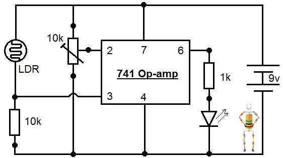
Parts Required & Circuit Diagram:
10k potentiometer,
10k & 1k LDR
741 Comparator op-amp
LED
9V voltage source
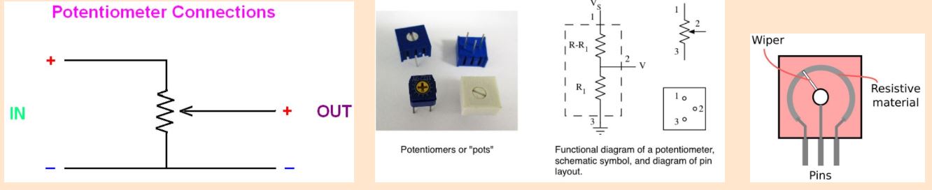
A potentiometer is an electrical component/device that can be adjusted
to provide an on-demand resistance (in a certain range) in a cicuit.
Picutres of potentiometers and schematic of them can be found in the
following figures:
This is a Light sensor circuit. Probably most simple and
interesting circuit to play with. It can be configured as either shadow
detector or Light detector, which means it can detect the intensity of
light. Right now in the circuit diagram it is configured as a Shadow
Detector, that means the LED will turn on when we show a bright light
over LDR. We can change this circuit as Light Detector by simply
swapping the pins 2 & 3 of 741 Comparator IC, and then LED will
turn on when LDR is dark. In this circuit, please make sure that pins
no 1,5 & 8 are not connected and left idle. Pin 6 is output pin. In
the circuit it is connected to an LED via 1K resistor, but you can also
connect a transistor to turn on a relay, motor or any other output.
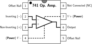
The Pin map of the 741 chip is:
Task 2: Build this circuit on a prototype board. Solder the components onto the board. Make sure use IC sockets for the 741 chip. Test your circuit and reord demonstration videos for the lab report.
3. Practice on soldering Surface Mount (SMT) components.
The instructor will provide some PCB board with SMT components for students to practice.
Task 3: Demonstrate that you are able to solder a SMT resistor to the pads and remove it from the pads on a PCB.
*
Show all the hand calculation, simulation, and oscilloscope measurement
as required in these tasks in your report for credits.
Follow the lab
report
guidelines
to avoid losing points.