Lab 1 Lab equipment and edit your webpage for your lab report.
Outcome of this lab:
1. Be familiar with the lab equipment.
2. Be able to edit your webpage and report your lab results to the website.
**If the
function generator (FG) is running in the '50 ohm' mode, the FG has a 50 ohm output impedance internally. The
displayed Vpp on the FG is only half of the signal that outputs.
You need to use a 50 ohm resistor to bridge the Positive and Negative
outputs of the FG to bring the output signal back to normal. This problem can be ingored if you turn the FG into the 'HZ' mode.
Instructions:
1. The DC (direct current) Power Supply
In
the following figure, you will find the power supply (voltage supply or
voltage source) in Fig. 1a, the 'Banana cable' in Fig. 1b, and the
connection between the cable and the power supply in Fig. 1c.

Fig. 1 The DC power supply
Keep in mind that we usually use the 'Red cable for the positive and the 'Black cable' for the negative.
Tasks:
1.1. Deliver a +5 V and a Ground line
to a breadboard. Take a picture of the board and the voltage
reading (on the power supply) for the lab report.
1.2. Deliver a +5.2 V and a Ground line to a breadboard. Take a picture of the board and the voltage reading (on the power supply) for the lab report.
2. The Multimeter
The cables are shown in
Fig. 2a, the multimeter is in Fig. 2b, the connections for voltage
measurement is in Fig. 2c, for current measurement is in Fig. 2d.
Always use the 'Red' one for positive and the 'Black' one for negative.
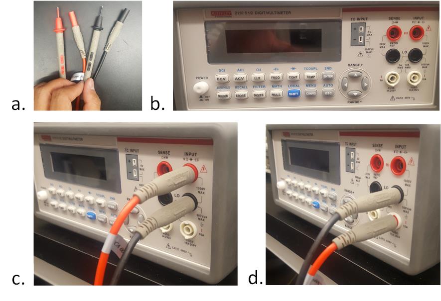
Fig. 2 The multimeter
Tasks:
2.1. Measure the 5 V on the breadboard and take a picture of the voltage readings on the multimeter.
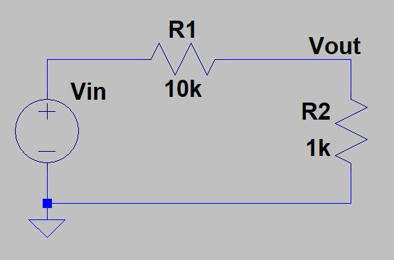
2.2. Build the following circuit on a breadboard, measure the current
flow in side the circuit. Take a picture of the current reading for the
report.
3. The function generator (FG) and the oscilloscope
Fig. 3a shows the cable for the FG, Fig. 3b shows the FG, and Fig. 3c shows the connection between the cable and the FG.
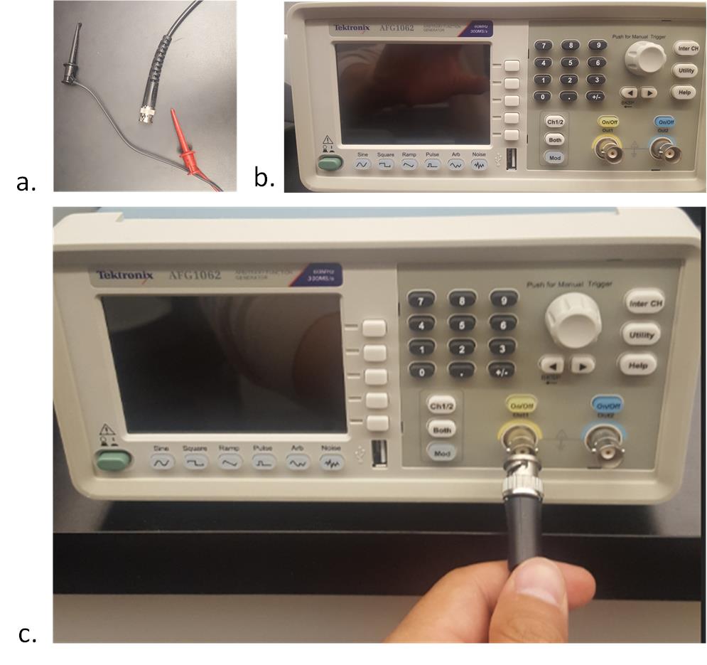
Fig.3 The function generator
Same
as the power supply, if you don't press the 'on/off' button, the
voltage waveforms won't be delivered to the output terminal.
The oscilloscope:
This
is the most complex equipment among these four, we will cover more
about it through the semester. Make sure you use the correct cable for
the oscilloscope:
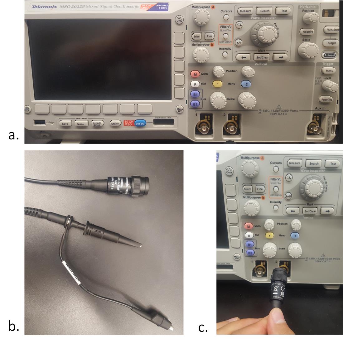
Fig. 4 The oscilloscope
Tasks:
3.1. Probe the standard signal (the
signal on the right side of the oscilloscope) from the oscilloscope.
What is the amplitude of the signal? What is the frequency? What is the
signal type?
3.2. Generate a 5 Vp-p, 1k Hz sine
wave from the function generator, deliver the signal to the breadboard,
probe the signal from breadboard using the oscilloscope. Take a picture
of the signal on the oscilloscope for the report.
** Report your results (with figures and texts) on the website.
Follow the lab report guidelines to avoid losing points.