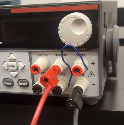
In the following figure, you will find the power supply (voltage supply or voltage source) in Fig. 1a, the 'Banana cable' in Fig. 1b, and the connection between the cable and the power supply in Fig. 1c.
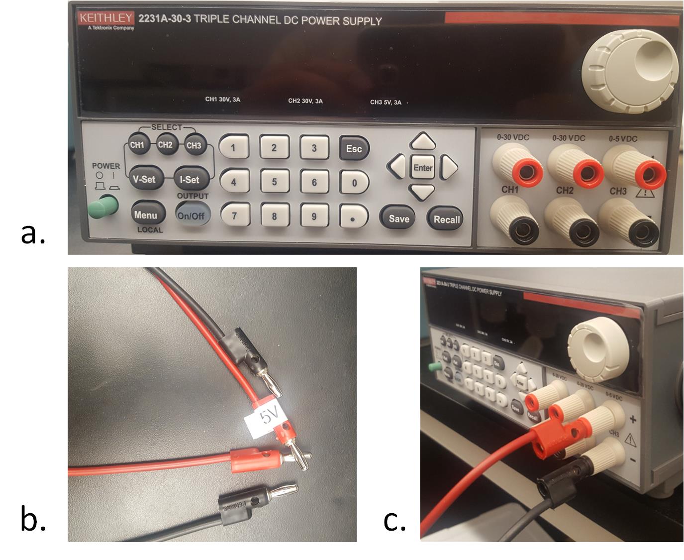
Fig. 1 The DC power supply
Remember we usually use the 'Red cable for the positive and the 'Black cable' for the negative.
Turn on the power supply, try to tune it to different voltage outputs by directly press the buttons for the demanded voltage output or turning the knob ot the top-left corner.
Press the button 'On\Off' to deliver/block the voltage to the output terminals.
2. The Multimeter:
The multimeter has its own cables, do not mess it up. The cables are in Fig. 2a, the multimeter is in Fig. 2b, the connections for voltage measurement is in Fig. 2c, for current measurement is in Fig. 2d. Always use the 'Red' one for positive and the 'Black' one for negative.
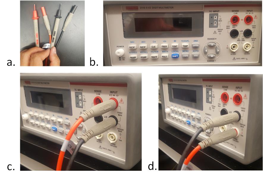
Fig. 2 The multimeter
3. The function generator (FG):
Fig. 3a shows the cable for the FG, Fig. 3b shows the FG, and Fig. 3c shows the connection between the cable and the FG.
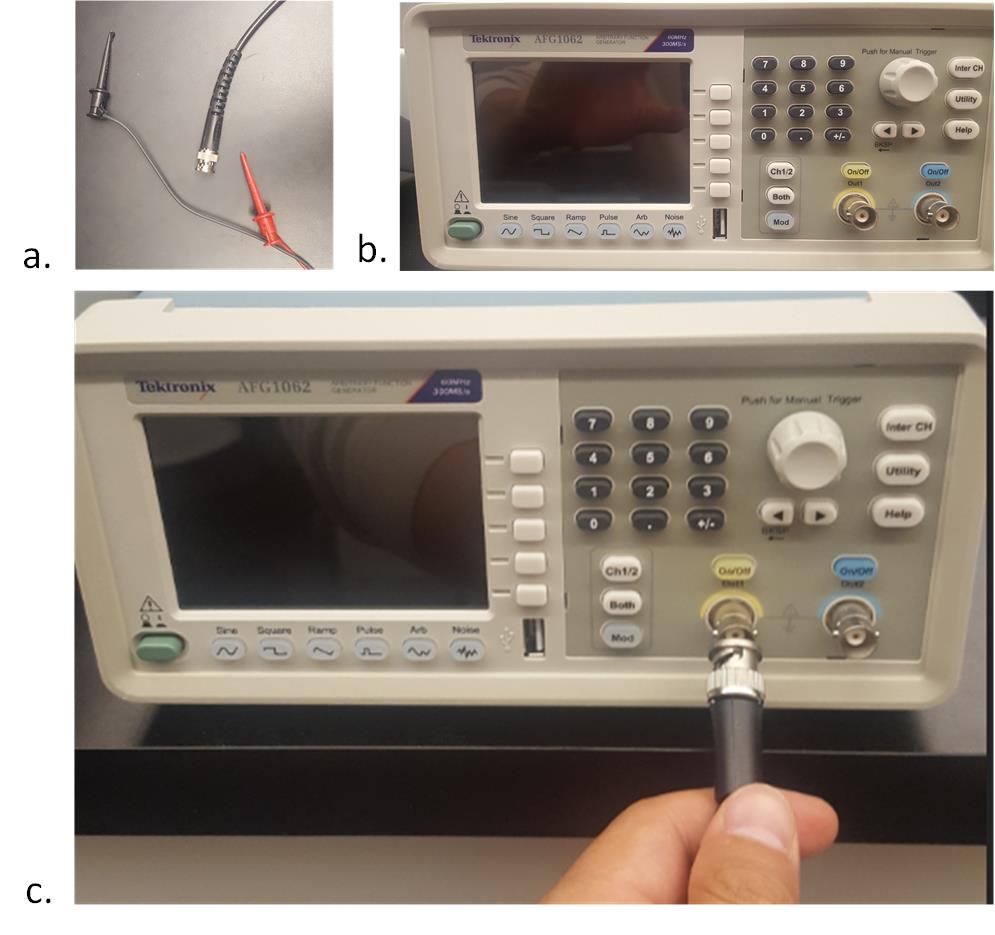
Fig.3 The function generator
Same as the power supply, if you don't press the 'on/off' button, the voltage waveforms won't be delivered to the output terminal.
4. The oscilloscope:
This is the most complex equipment among these four, we will cover more about it through the semester. Make sure you use the correct cable for the oscilloscope:
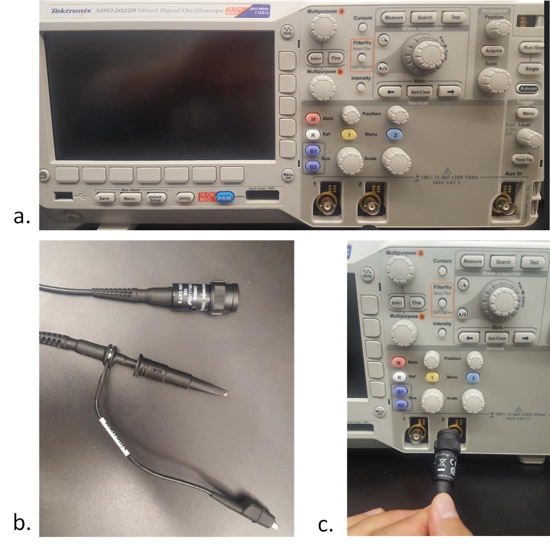
Fig. 4 The oscilloscope
Tasks:
(Take pictures of the results use you smartphone for your lab report)
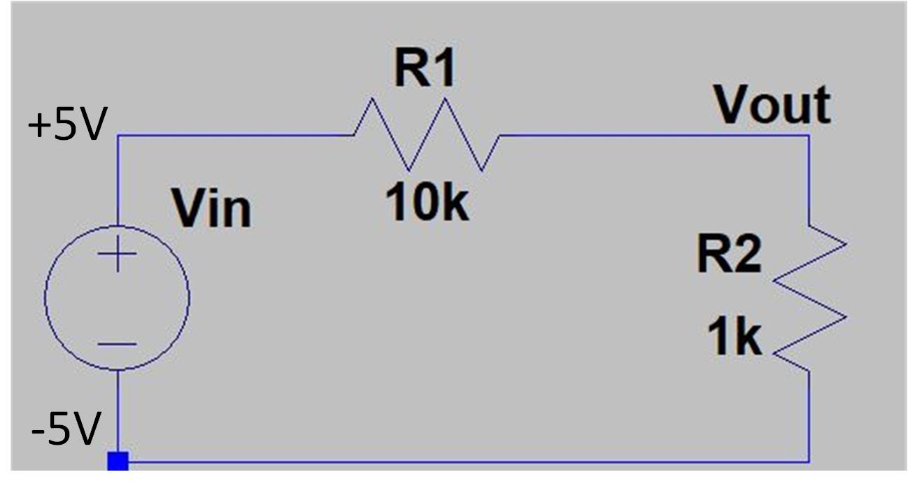
1. Build a circuit on a breadboard as follows:
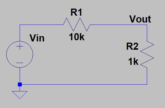
Give Vin 5V, and mearsure Vout use the multimeter.
2. The same circuit, give Vin -5V, measure the Vout