Horseshoe IMU Wireless Communication

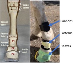
Commercial IMU sensors being wrapped to the Cannon bones, the pasterns,
and on the side of the hooves which is subject to inconsistent wrapping
locations.
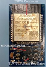
The developed prototype of the horseshoe
embedded IMU system.
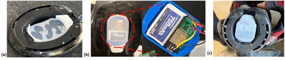
In the following figures (a) - (c):
(a) 3D printed minimalist base plate bracket that can attach to a pad. (b)
Electronics pack with ESP-32, MPU, and battery attached to a horseshoe. The
other side of the bracket carries a custom circuit board and a 3.7V battery
with a power switch. (c) A completed module and the system being mounted (twist
and lock) to a horse hoof.
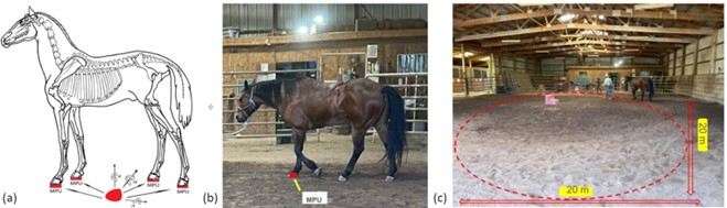
For the following figues (a) - (c):
At the barn to
collect preliminary results of the embedded sensor from a horse. (a) IMU system
locations. (b) Horse setup with a MPU sensor for data collection. (c) Horse
walking in circle with an IMU attached to a horseshoe for data collection.
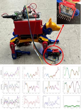
The robot dog used for gathering preliminary
results from the IMU prototype.
References:
1. ESP32 tutorial 1
2. ESP32 tutorial 2