Lab 07 Self-defined libraries and the PSU schematic
Three ways of including self-defined libraries into your Eagle library folder:
1. Draw both the schematic (symbol) and footprint from scratch.
2.
Import or draw the schematic (symbol) and import the footprint from
other parts (most of the packages are standard packages).
3. Download both schematic (symbol) and footprint from SnapEDA and import them into your library.
In
this lab, we will try all the three methods listed above. The most
frequently used method for me in my practice is method No. 2. However,
you should know how to create a part using all three methods.
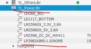
I
already have a library called YL_others.lbr. You can create a library
called "E393_Power", "E393_Switch", etc and start creating devices
within these libraries.
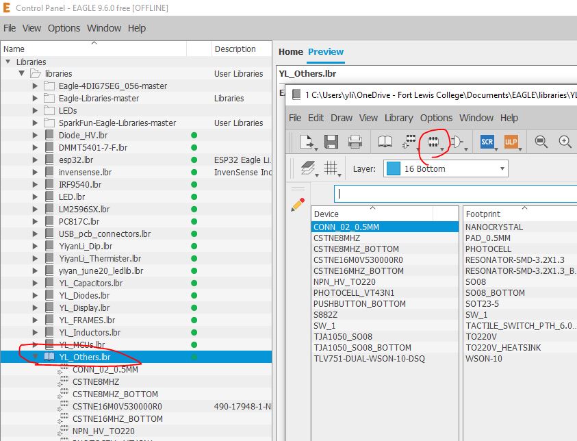
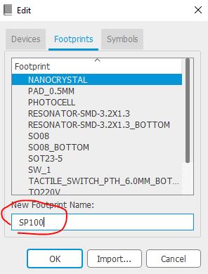
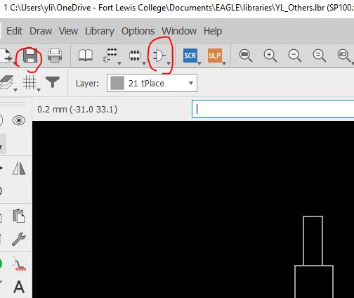
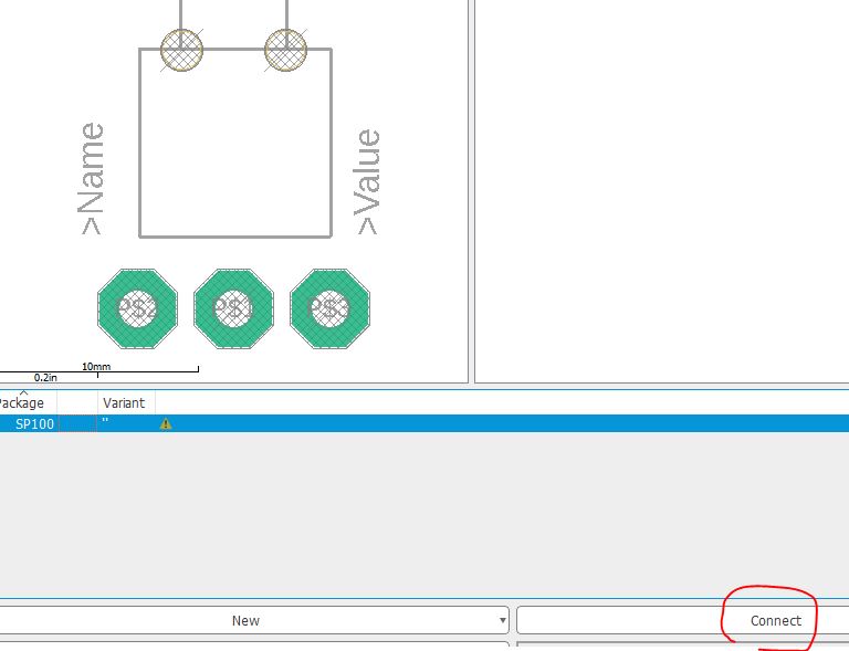
Create a new footprint called SP100.
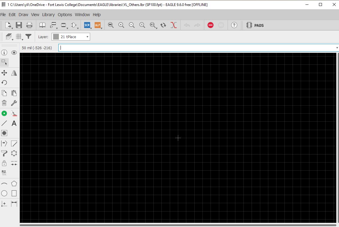
Slightly adjust the grid for your drawing.

Change the unit to mm first before you change the size.

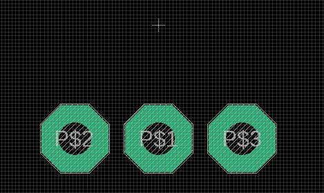
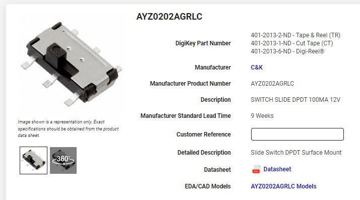
We are creating the following switch for this lab. Here is the link to the part. You can see that it is basically three through-holes and two drilled holes.
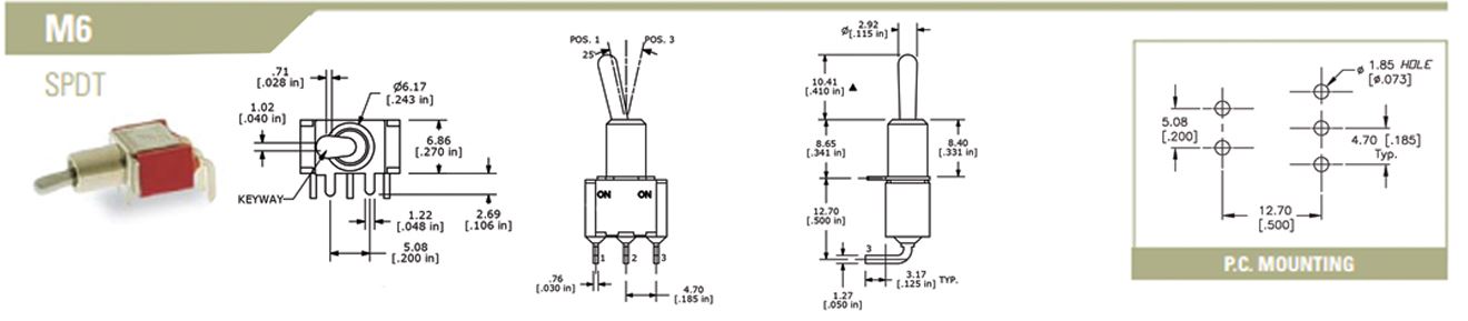
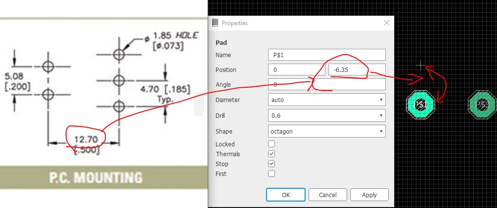
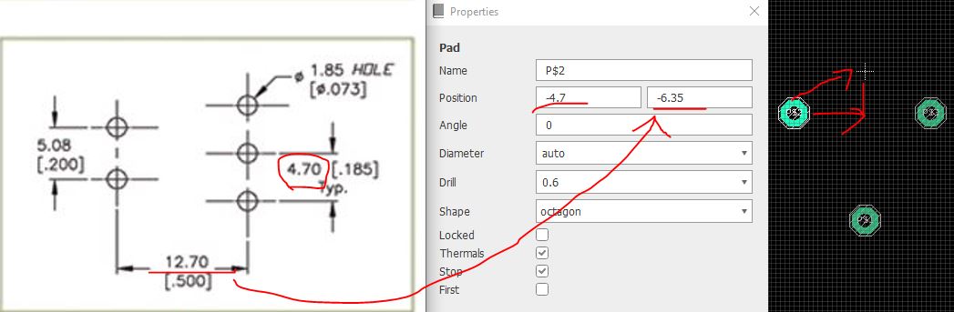
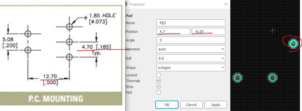
Place three through holes in the editor.
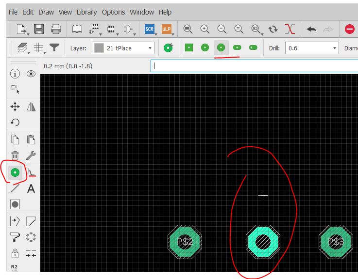
Refer to the sizes, diameter, space, and other dimensions you can see in the datasheet to make certain changes to your drawing.


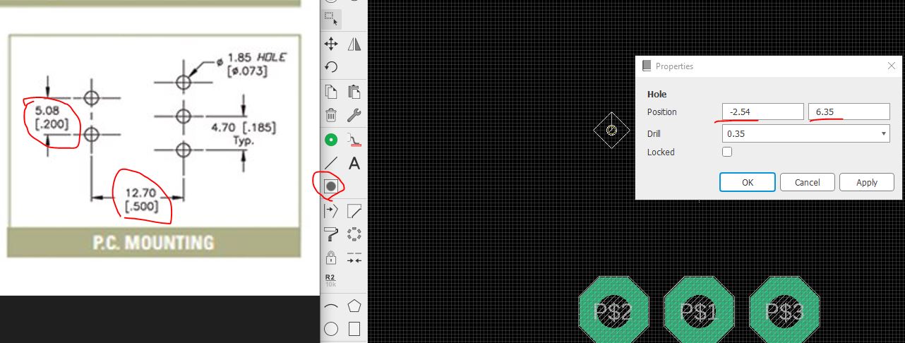

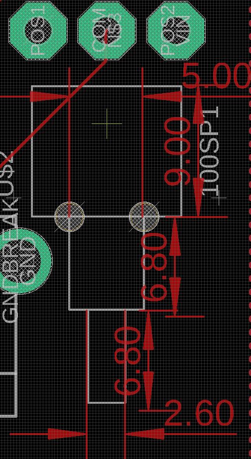
The
following snapshot came from Dr. Coulston's layout example he shared
with me. I don't want you to waste your time on measuring the dimension
of the switch so I just measured in Eagle and showed them in the
following snapshot. The unit is mm.
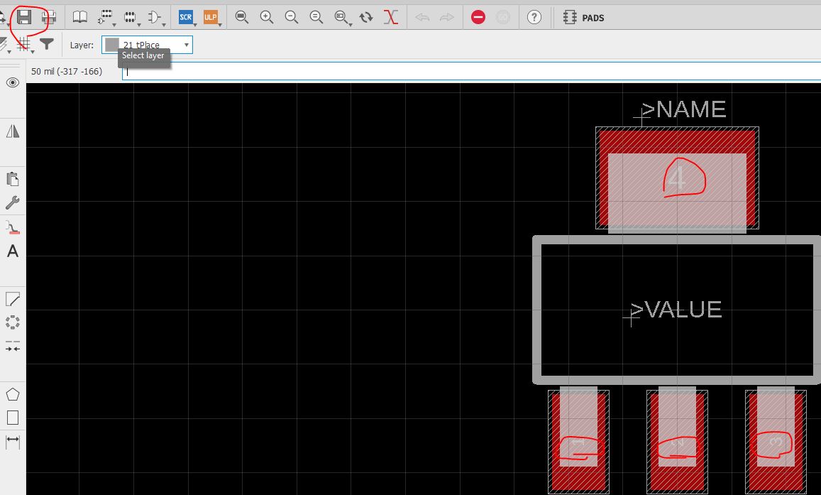
Add
>Name and >Value at the tName and tValue layers. 't' means top,
'>' indicates a variable not a static text. It'll display the real
name and value in your layout.


Save
it. Now let's create a symbol for it. It is not difficult to find a
Switch symbol from other parts. Since this is to teach you how to draw
everything from scratch, so let's draw it.
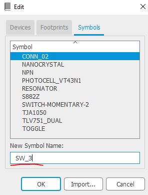
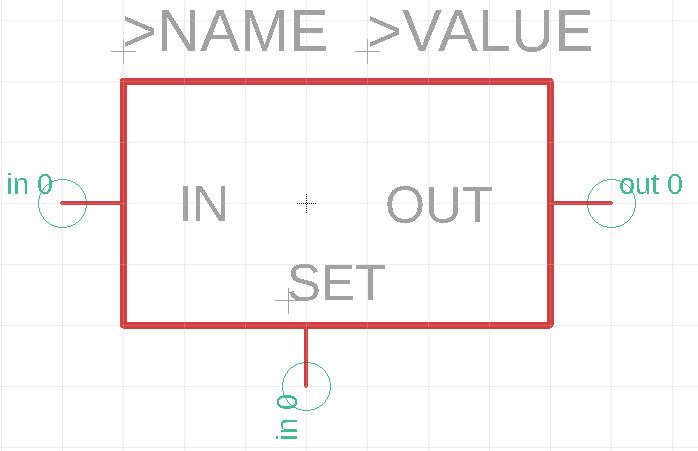
Create a new symbol.
Place
circles and lines to make it like a switch for your schematic. To make
the circle smaller, press 'Alt' when you move your mouse will activate
the finer grid and allows you to make it smaller.
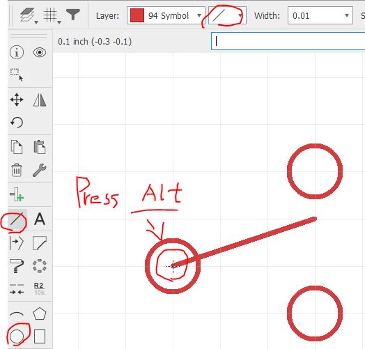
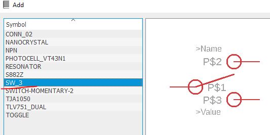
Place
three pins. Note that the circles and lines have no electrical
properties; they are merely drawings. The pins are the ports that will
be bound to the layout pins.

Add >Name and >Value at the tName and tValue layers.
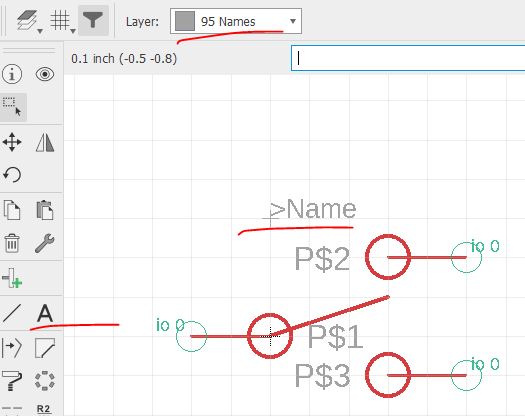
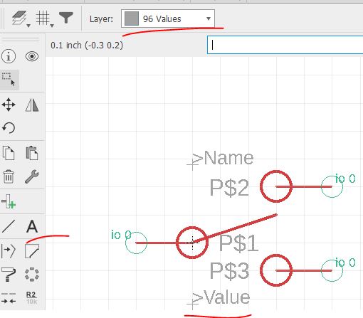
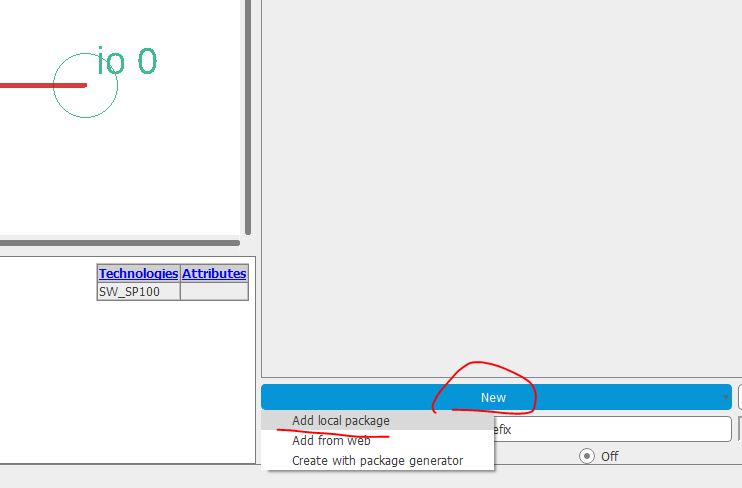
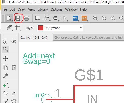
To
turn off the P$1/2/3 display, right click the pin tip (inside the green
circle), properties - choose 'off' for the bottom drop-down menu.

Save it. Now let's create a device that put the symbol and the footprint together.

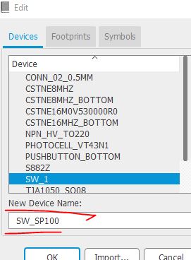
Give
the device a name. This name will be the name of the part shows up in
your library. When you search for parts in the library for your
schematic, this name shows up.
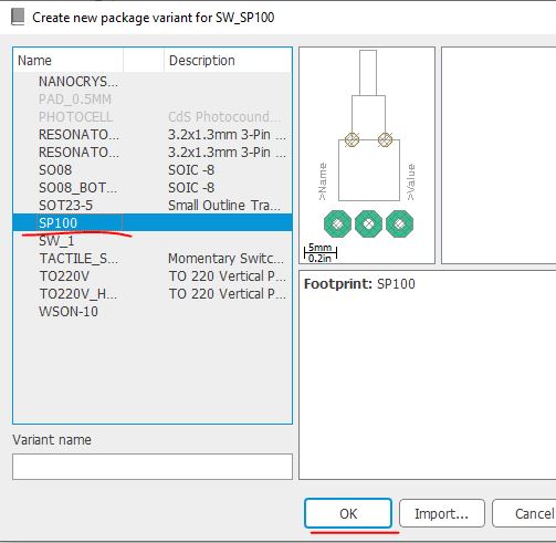
Place the previously created symbol here.

Place the previously created footprint here.
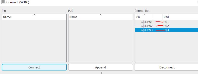
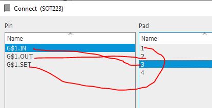
Let's
connect the pins in the symbol to the pins in the footprint so Eagle
knows which through-hole in your footprint represents which pin of the
chip.
Change
the order when necessary. You must refer to the datasheet and the
pinout of the chip to make sure you know what you are doing here.

Save it.
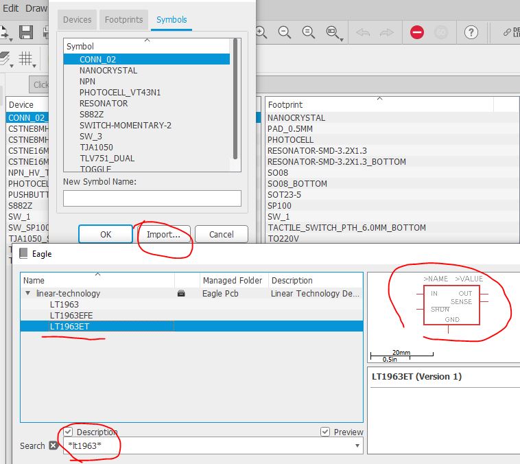
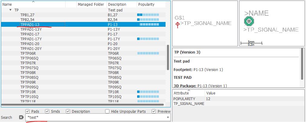
Next device to create is LT3080, which is a voltage regulator. I would create it in my YL_Power library.

This time, we'll try to import both the symbol and the footpring from other parts available in Eagle.
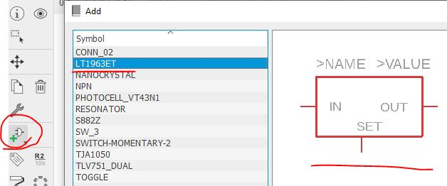
The
voltage regulator's symbol is not a new thing. Most of them look very
similar. I searched in Eagle and found the following symbol. At least
it saves me several minutes to draw the box, the pins, and other
things. So let's import it.
Edit it slightly so it matches the pinout of the LT3080 chip.
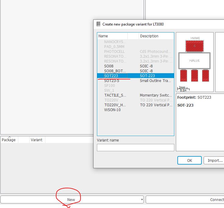
Now
let's import a SOT-223 footprint from the library. this is an extremely
common package (footprint) so it'll be an easy process to find it.
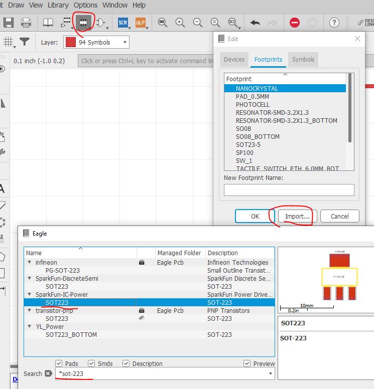
Footprint found. Save it.
Now, within your library, create a new device called LT3080.

Load the symbol and the footprint you just "stole' from other parts.
From
the datasheet you found that the tab is shorted to OUT. Theoretically
these two pins are internally shorted and we don't need to do anything
to the tab. To be safe, we'll still connect the tab to OUT.

See the following table, you found that there is a pin 4 (the tab) in the footprint but the symbol only has three pins.
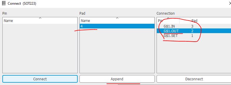
For the last one, use "Append" to short them together.
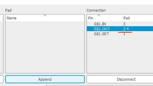
Done and save it.
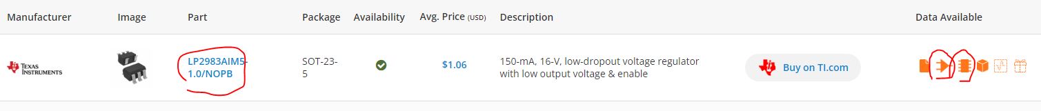
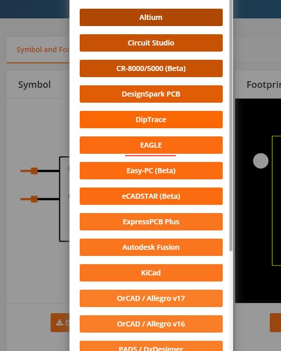
Now
let's use the third method to load parts to your library - directly
download them from SnapEDA. Follow Dr. Coulston's instruction to
download the following parts.
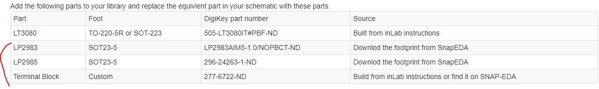
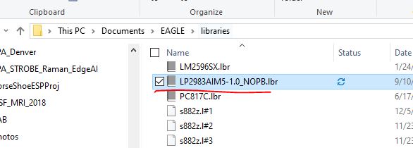
Make sure you 'Use' it so it is visible when you import it to the library.

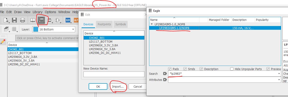
Do the same thing for LP2985.
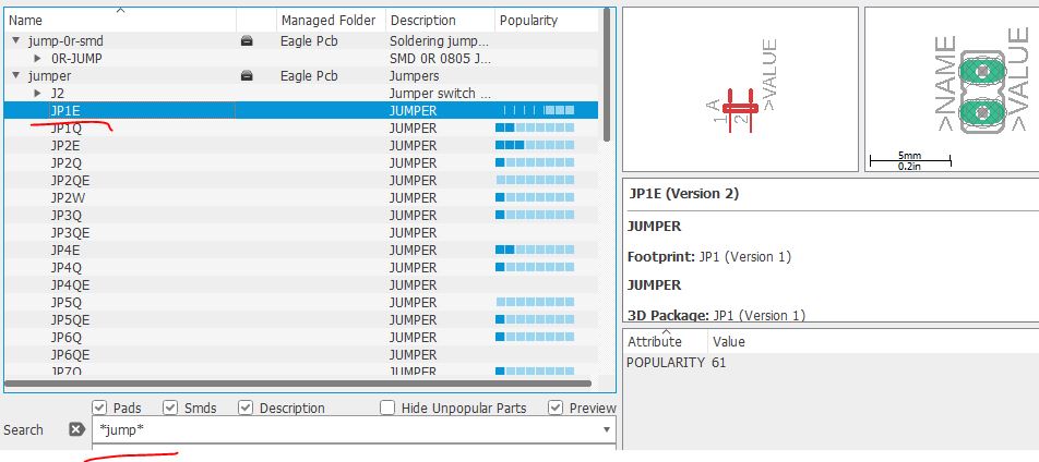
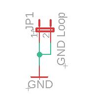
Now
let's work on the terminal connector. It is the terminal that provides
voltage output. I found the following part from SnapEDA. There are only
two ports although the image on the left shows more.

Terminal: 1935161 footprint & symbol by Phoenix Contact | SnapMagic Search (snapeda.com)
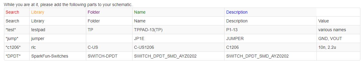
It's almost there. Add the following parts according to Dr. Coulston's instruction.

Add V_SET and I_SET to the OpAmp inputs shown below.
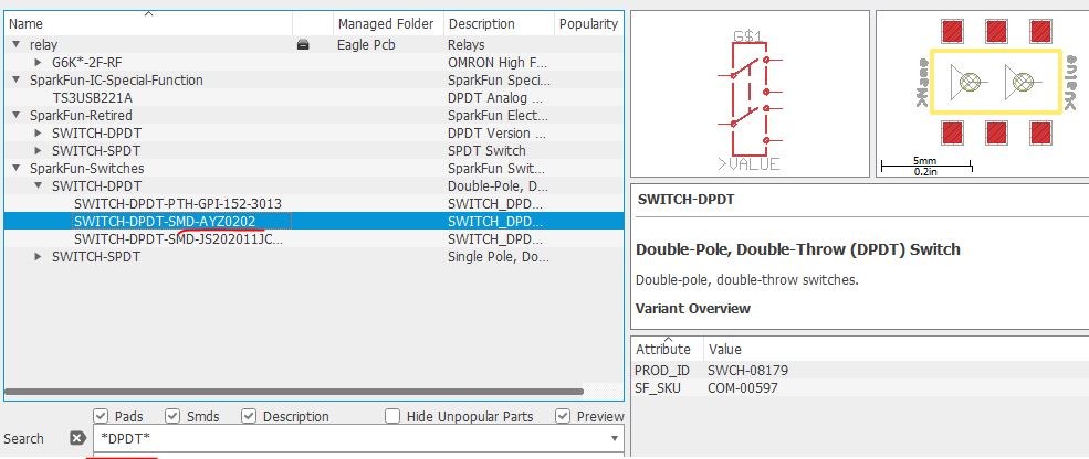
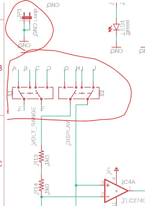
The
two DPDT switches that have A - J connections are surface mount 4-2
slide switches. There is only one slide on it so it either sends the
first/third pins to the output or the second/fourth pins to the
outputs. The switch was found on DigiKey:
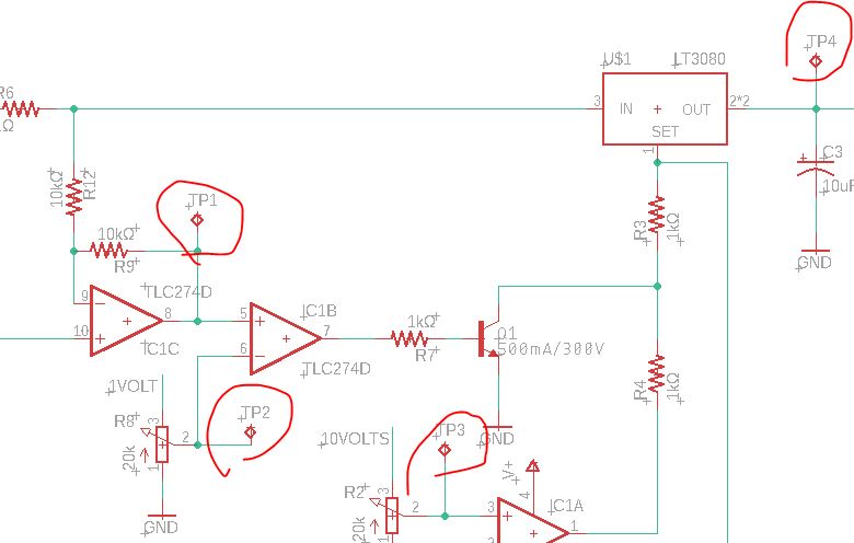
Here
is the task description from Dr. Coulston's Lab07 website. Please
follow it and complete the connections of the DPDT switches so the VU
meter is able to show the real-time Vout/Iout or V_SET/I_SET.
(hint:
the 1V and 10V outputs from the regulators are reference voltages for
the VU meter so one of them must be sent to V-range of the ladder).

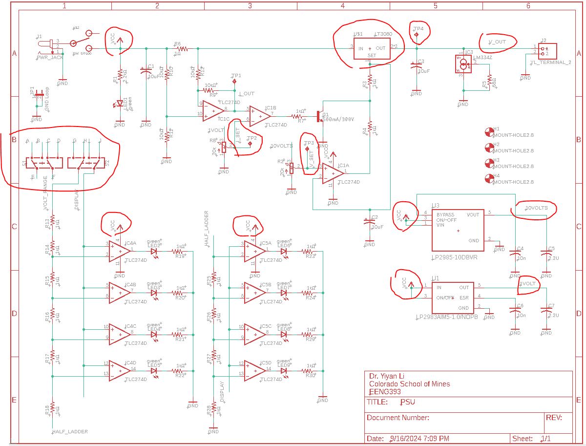
Here is my printed schematic. (without DPDT switch connections)