Lab 01 Test the board
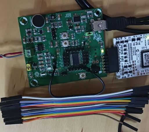
Initial setup.
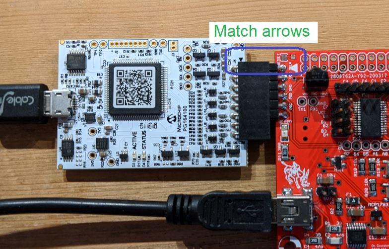
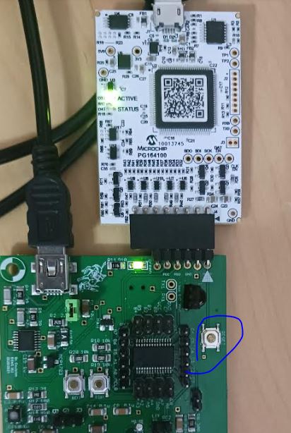
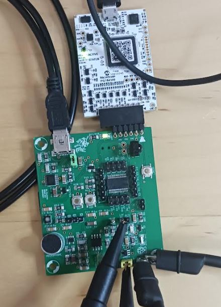
Connect the development
board to your computer first, then the Snap debugger to the computer,
then the Snap board to the development board.
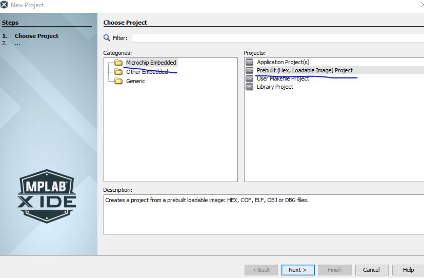
After the hardware connections are done, create a new project from file - new project.
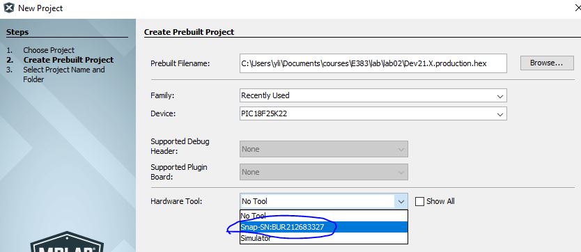
Place this hex file in the directory of this lab. (right click and select Save Link As).
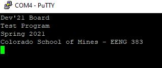
Click the Play button. The connections are good if you see the following message in the Output window
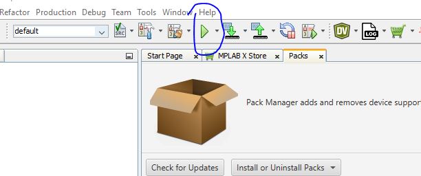

It
may fail several times before you reach the desired output above. If it
fails, unplug the debugger and plug it back in to see if it
changes.
1. Test #1 - Test RS232 Communication link
Download and instll PuTTY

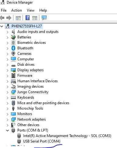
Keep both the PIC board and the Programmer board plugged in. Open Device Manager to find the COM port number.
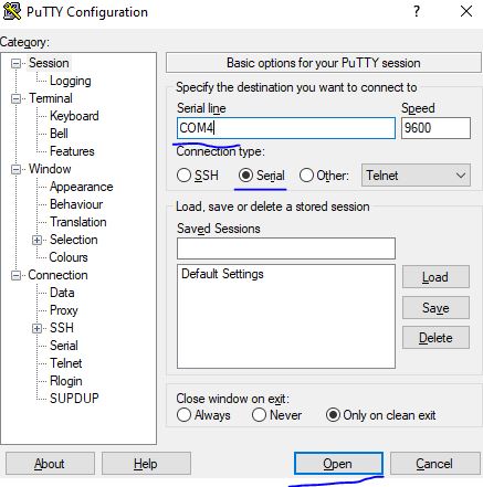
Open PuTTY, configure it as follows.
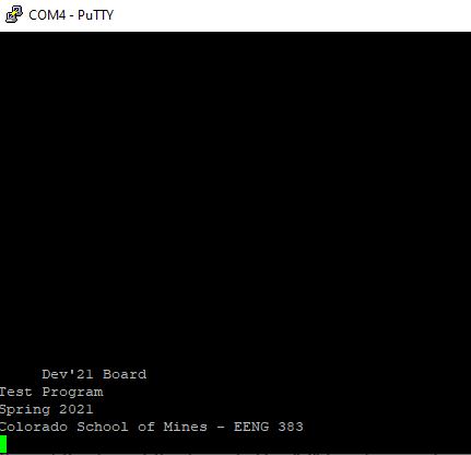
Press the "Reset" button on the board to display the starting texts on on the monitor.
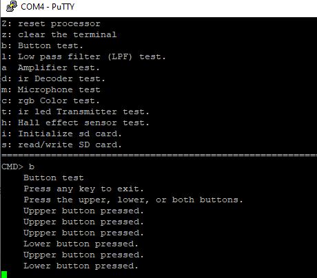
Type a "?" to show more instructions on the monitor.

2. Test #2
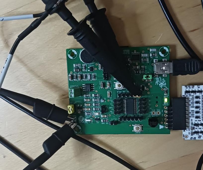
The
table lists all the connections and configurations that need to be done
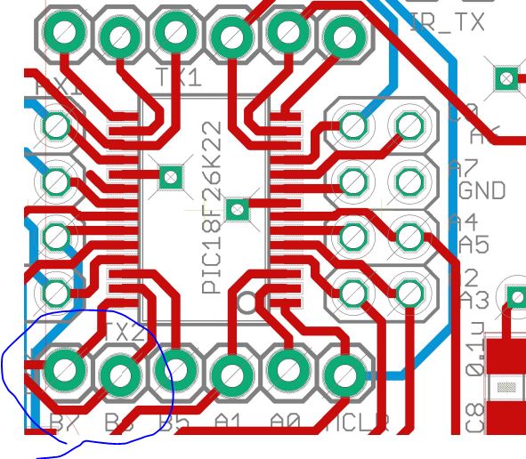
for this task. The two channels of probes are connected to RB6 and RB7.
On the board, it shows B6 and B7. Link to the layout and schematic.
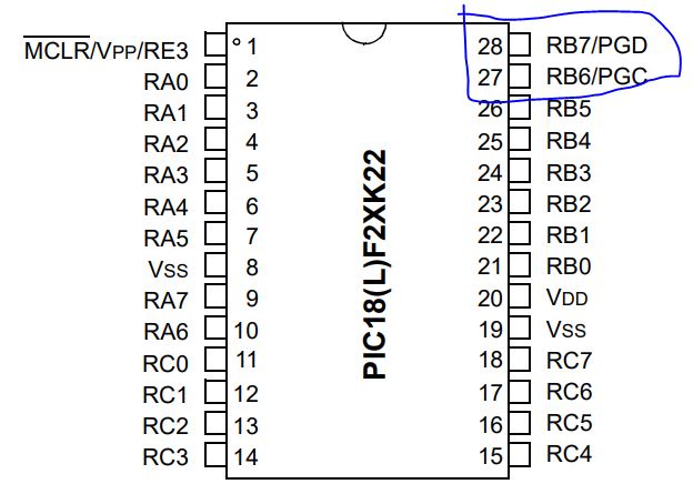
Use an oscilliscope to probe RB6 and RB7.
You can find more details on the MCU's datasheet.
Display them on the oscilliscope. Use Run/Stop to get a steady image.
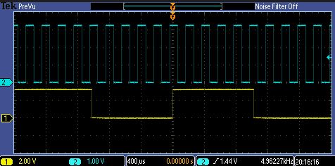
What are the frequencies of these two signals?
3. Test #3 Test terminal
Type a "Z" in the terminal to reset the MCU. You should be able to see the following results.
4. Test #4 Test buttons
Follow the instruction to get the following results
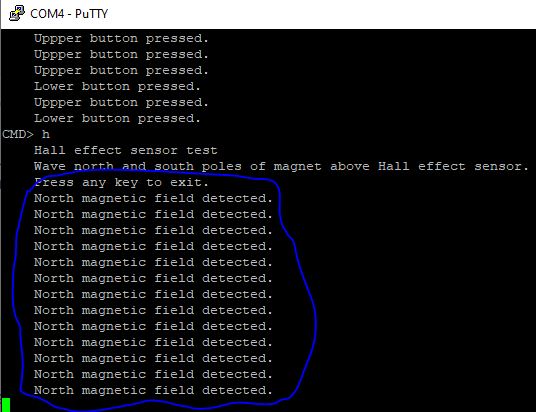
5. Test #5 Hall effect
From the schematic, I found that IC3 is the sensor.
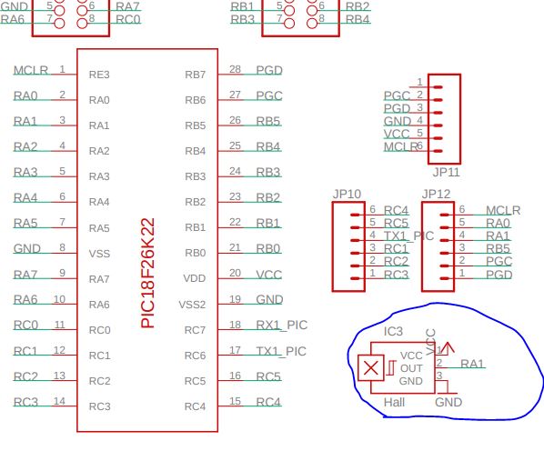
Then
looking for IC3 from the layout. "IC3" was not labeled on the layout
but "Hall" was. I found it through the connection "RA1" on the
schematic and traced down to the chip.

I
grabbed a magnet from the safety switch of my treadmill at home and it
only shows the North pole because the other side is covered by
plastics. Pleae don't use the spearker's magnet for this task.
6. Test #6 Test microphone
When
you press "m" at the command prompt, the PIC will test the microphone.
The microphone continuously provides the amplitude of the sound wave to
the PIC which when it samples the sound wave converts this amplitude
into an 8-bit value between 0 and 255. This function provides 16
samples, each 100us apart. The samples are collected as soon as you
press a key (after pressing "m").
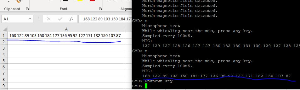
If
you select the data, it should have been put into the buffer so
directly paste it into an cell of an excel sheet. Split the values into
columns using the "Text to Columns" option.

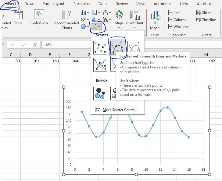
Insert a chart.
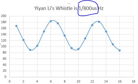
Change
the title. According the tutorial, it samples at 100 us intervals. A
period of my whistle has about 8 points so the period is 800 us and the
frequency is 1/800us Hz.
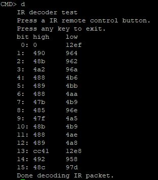
7. Test #7 Remote control
When
you press "d" at the command prompt, the PIC will test the remote
control decoder. The IR remote control decoder sensor is able to
translate the IR energy emitted by most remote controls into a series
of logic-level pulses. This little application will tell you the length
of the first 16 of these pulses. After hitting "d" at the command
prompt, grab any handy remote control, point it towards the dome shape
on the IR decoder and press a button. You should immediately see a
series of numbers appear on your terminal.
8. Test #9 Test Low Pass Filter
When you press "l" at the command prompt, the PIC will test the low pass filter.
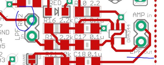
Place a jumper at RC2/LPFin, and a jumper at LPFout/AMPin. Probe the top of these two jumpers. :
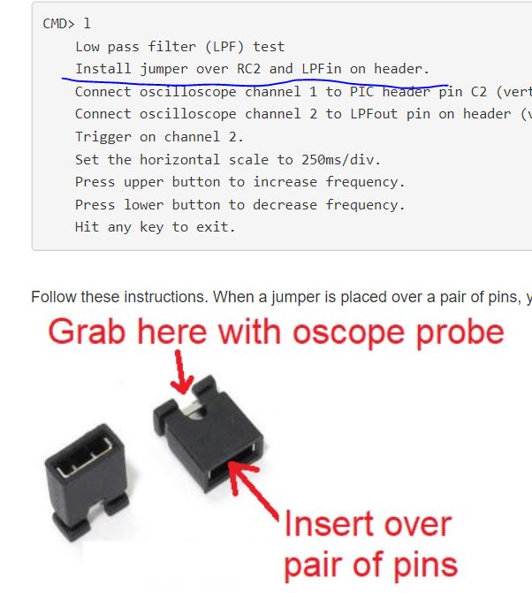
You should see this:
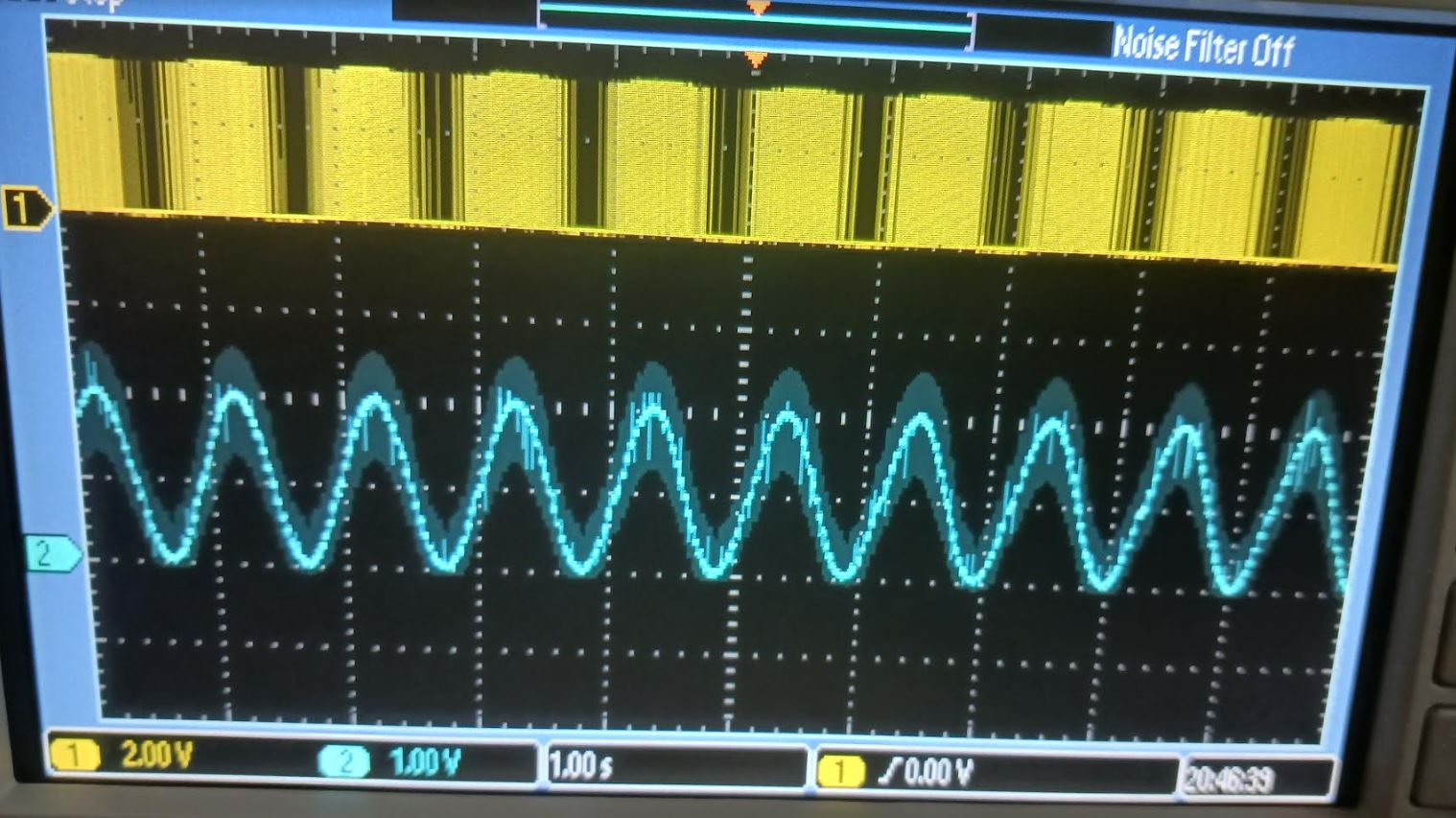
RC2 outpus a PWM (digital signal) which is fed into a LPF to get modulated. The LPF converts the digital PWM into a sinewave.
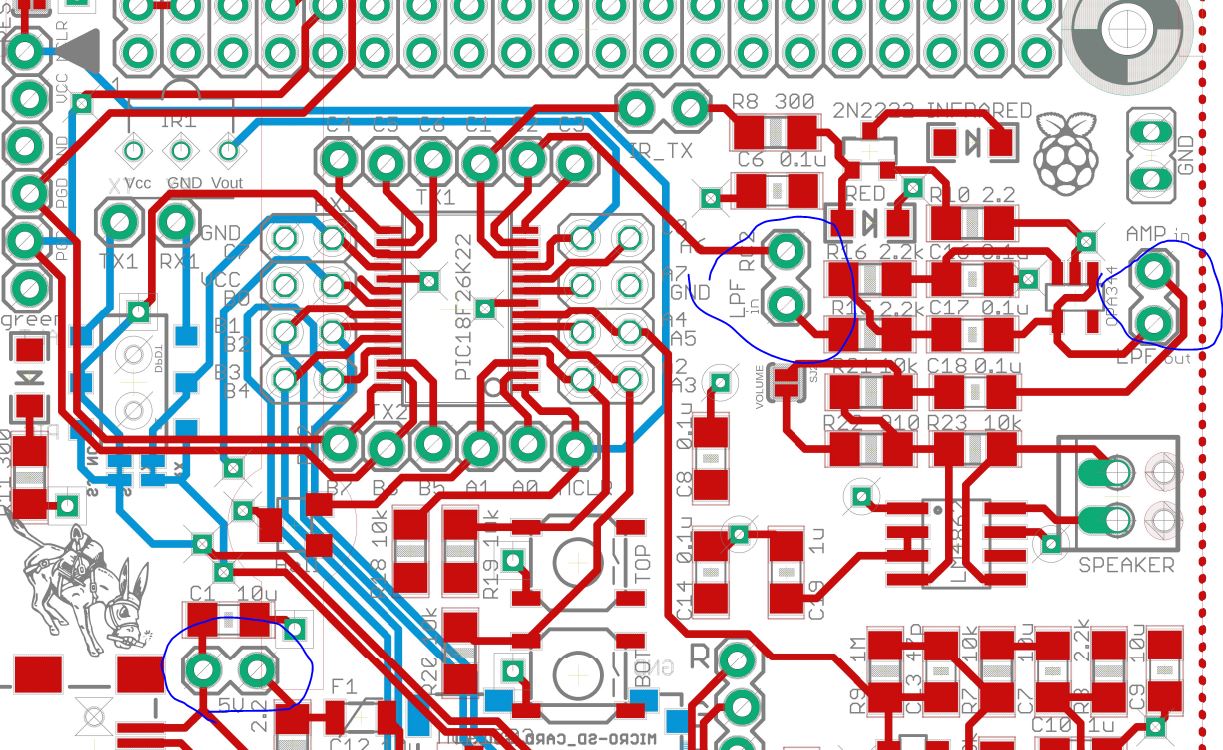
Here is the LPF on the schematic
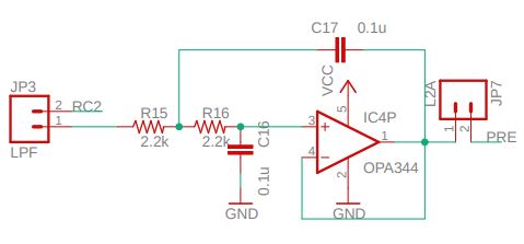
RC2 and LPF out can be found here
9. Test #10 Amplifer
This snapshop does show that the MCU enters the Amplifier mode. Follow the procedure outlined on the serial monitor, you should be able to hear sounds form the speaker.
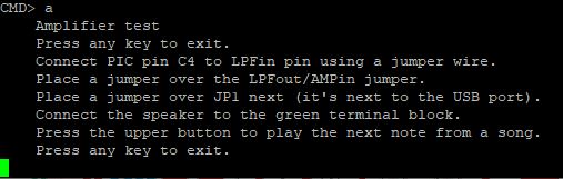
C4
and LPFin are not next to each other. If you put a Jumper (not a Jumper
Wire) at RC2/LPFin (C4 not C2), it won't work. The instruction asks you to connect
C4 to LPFin, so you need a longer wire to connect these two pins.
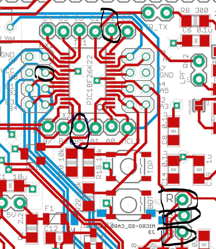
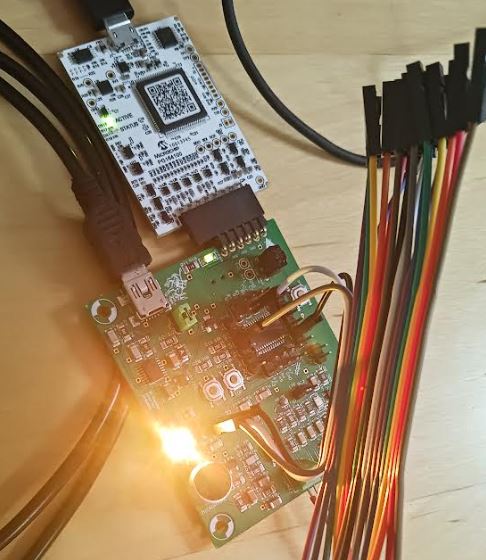
10. Test #11 The RGB LED
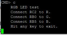
Make the connections according to the instructions on the serial monitor.
-------------------------
Tasks: (10 points for each Test)
1. Complete Test #1, show serial monitor snapshots for credits.
2. Complete Test #2, show socillscope snapshot for credits. What are the frequencies of these two signals?
3. Complete Test #3 - #5, show serial monitor snapshots for credits.
4. Complete Test #6, show serial monitor snapshots and excel plotted figure snapshots for credits.
5. Complete Test #7, show serial monitor snapshot for credits.
6. Complete Test #9, show socillscope snapshot for credits.
7. Complete Test #10, demonstrate to TA of the instructor for credits.
8. Complete Test #11, show a photo of the yellow light on your report for credits.