Lab 1 Gvim installation, Vim commands, Vivado installation, and the first FPGA simulation
Use your personal laptop is highly recommended.
If you have a text editor similar to gvim, please ask my permission to use it in this lab.
1. Use gvim
gvim must be used for most of the coding practices. Tutorial
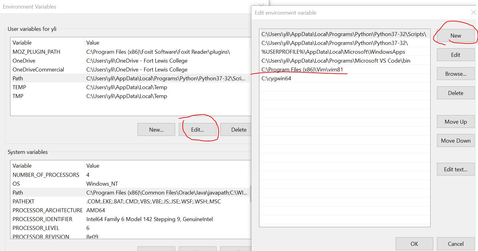
To start gvim in your command line window, you must add the path to
gvim to the Path environment variable. Press the 'Windows' key on the
keyboard, type 'edit the system environment variables', then add the
path to gvim to the Path variable.
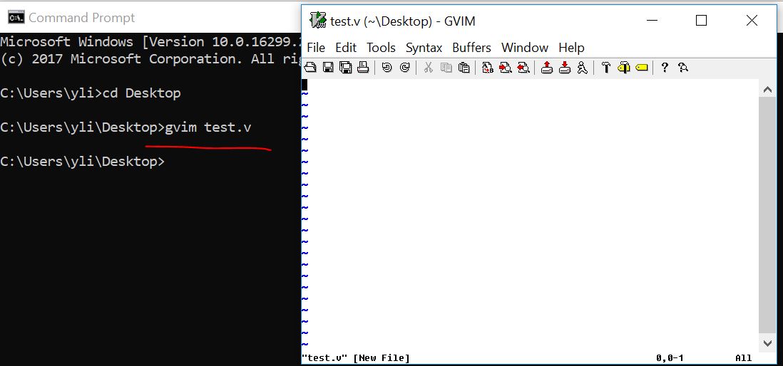
Now, you should be able to start gvim in the command line window:
Practice the commands in the gVim editor. The following commands will be on the quiz:
:e [file] - Opens a file, where [file] is the name of the file you want opened
:w - Saves the file you are working on
:wq - Save your file and close Vim
:q! - Quit without first saving the file you were working on
:set number - label the lines with numbers
:norm i# - comment line/lines
:norm x - uncomment line/lines
:new filename.py - create a new .py file in the same directory. The new file will be opened below the current edit window
:vert new filename.py - create a new .py file in the same directory. The new file will be opened beside the current edit window
:set guifont=* - set the font style and font size
h - Moves the cursor to the left
l - Moves the cursor to the right
j - Moves the cursor down one line
k - Moves the cursor up one line
$ - Places the cursor at the end of a line
Ctrl+ww - switch cursor among different vim windows
gg - Places the cursor at the start of the file
G - Places the cursor at the end of the file
i - insert in front of the cursor
a - instert after the cursor
I - insert at the beginning of the line
A - insert at the end of the line
o (ou, not zero) - start a new line below
O (ou, not zero) - start a new line above
yy - Copies a line
v - Highlight one character at a time using arrow buttons or the h, k, j, l buttons
V - Highlights one line, and movement keys can allow you to highlight additional lines
p - Paste whatever has been copied to the unnamed register
dd - Deletes a line of text
x - Deletes a single character
u - Undo the last operation; u# allows you to undo multiple actions
Ctrl+r - Redo the last undo
r - replace the current letter to something else. Just type the updated letter after you type 'r':
:lefta vsp xxxx.v - open a file on the and display it on the left side of the current file.
2. Vivado Installation
This
tutorial uses the Vivado 2017 version. The newer versions (newer than
2020) are too large for personal laptops. We recommend the 2017 or
the 2018 versions for this class. The instruction on Vivado
2018.3 installation can be found here.
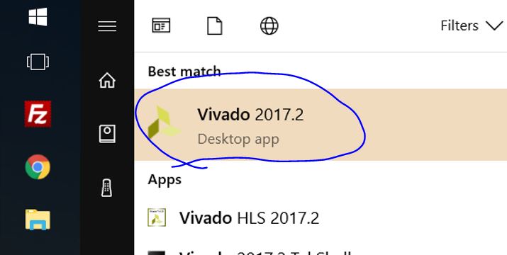
Open Vivado Webpack from your desktop (press the 'window' button on
the keyboard, and type 'vivado').
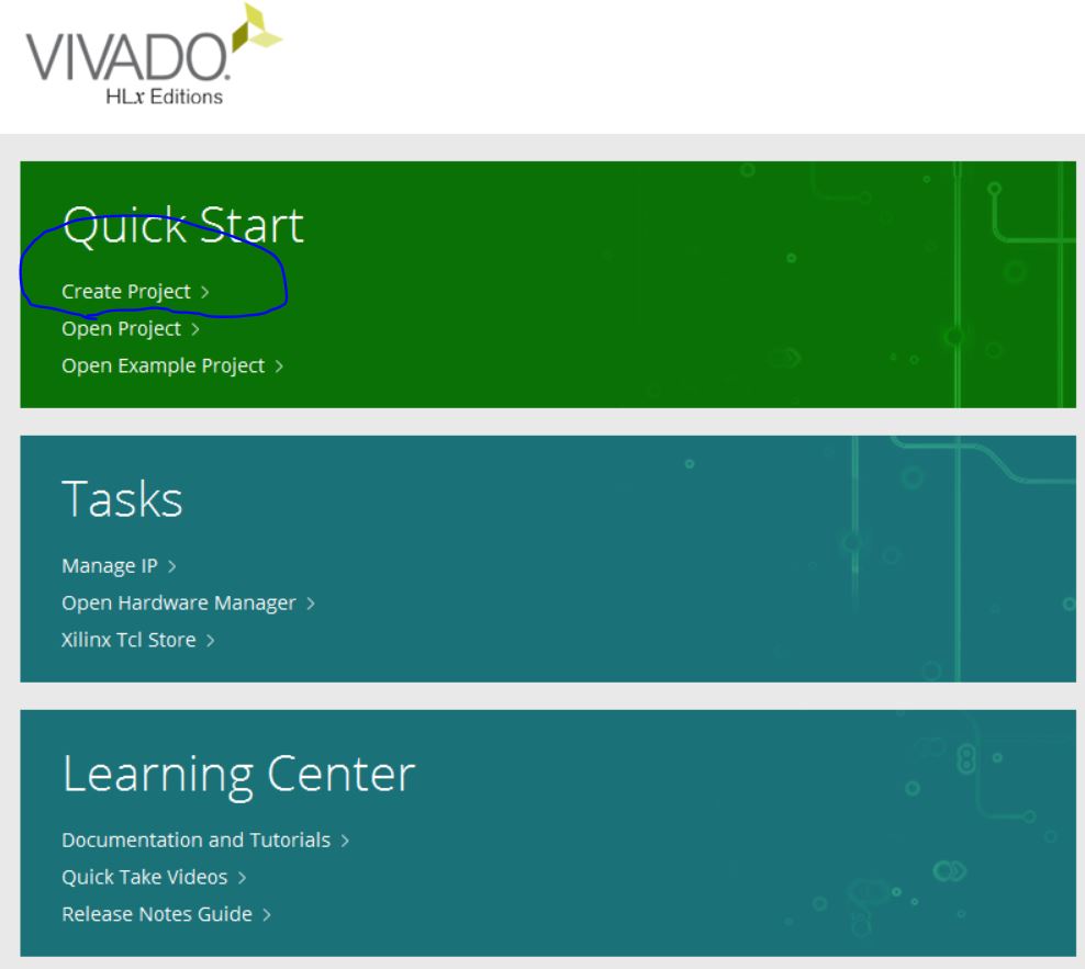
Create a new project:
Put your project folder in a proper directory (no space in the
project name and the directory):

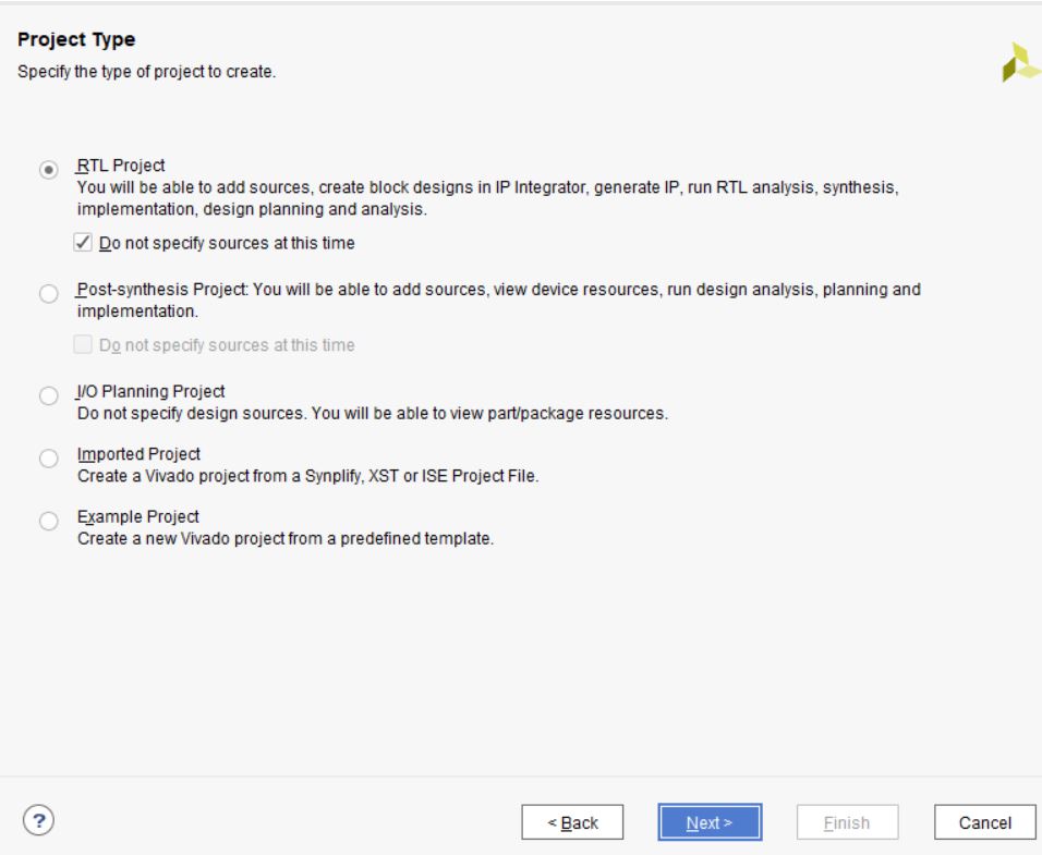
Select 'RTL' project:
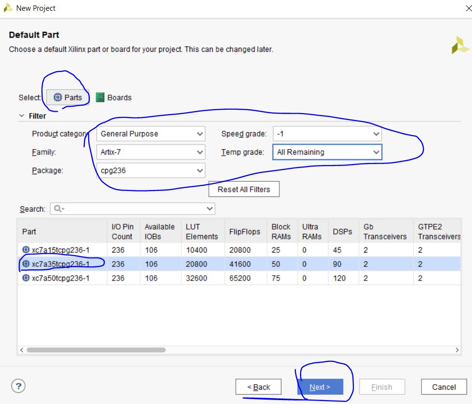
Select the correct chipset for your FPGA board. Our Basys 3 board has
an ARTIX-7 FPGA chipset, the part number is: xc7a35tcp236-1.

Let's start making an AND gate using Vivado and run some simulations.
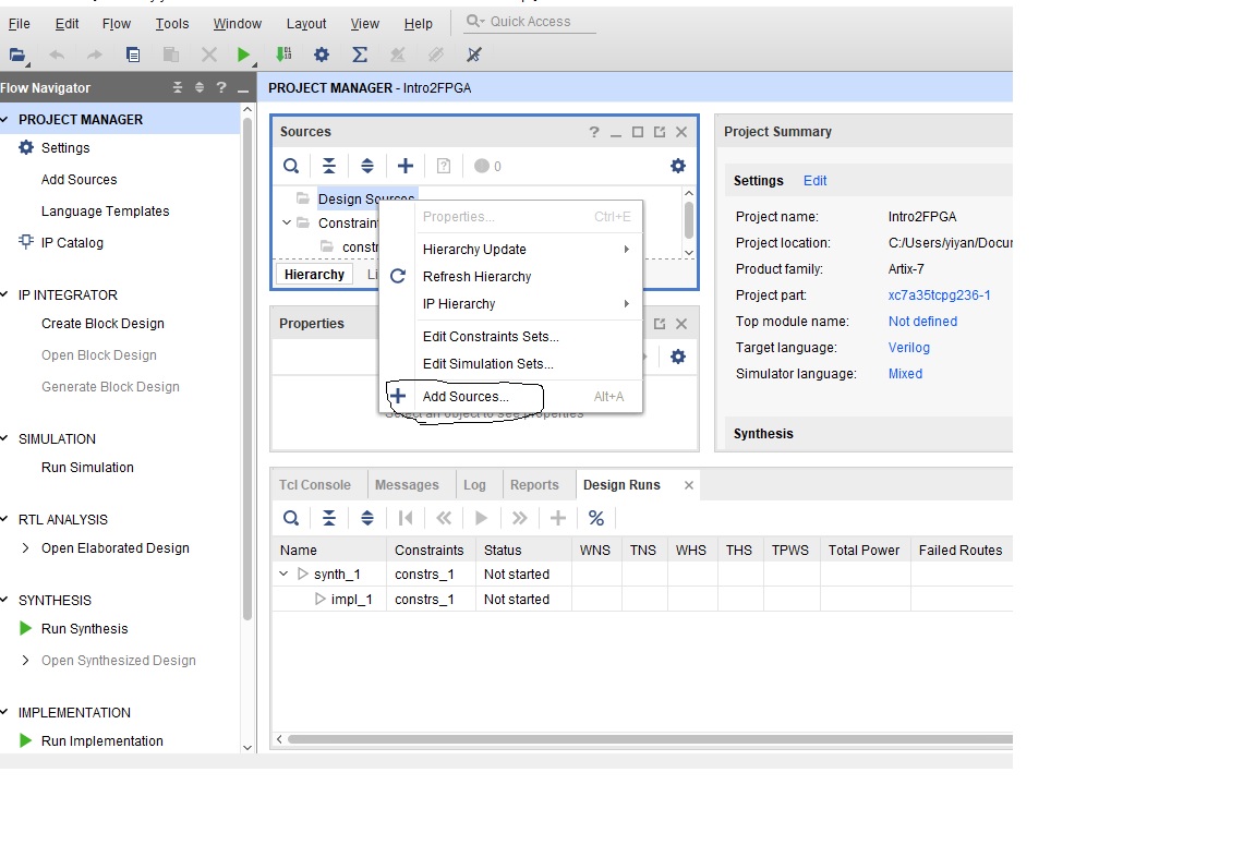
Right click 'Design Sources' in the Sources window, click 'Add
Sources'.
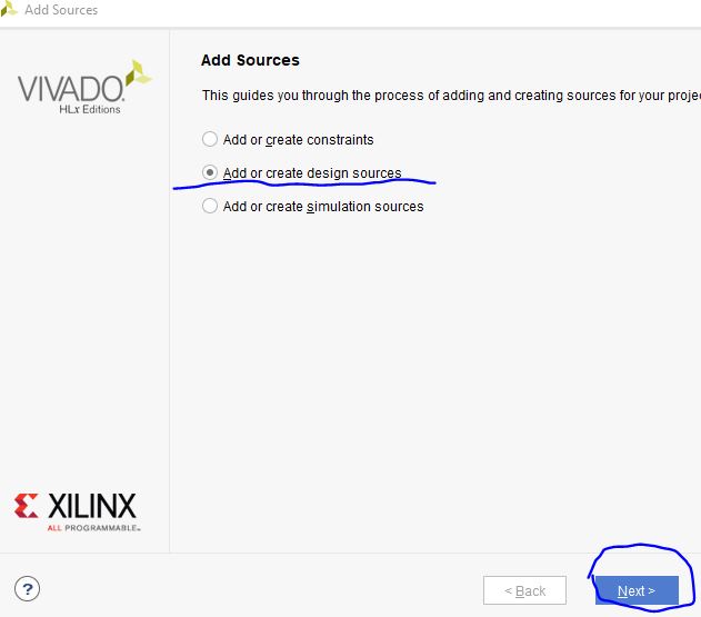
Select Add or Create design sources, and click 'Next'.
Create your first Verilog file, name it as AndGate, and click 'Finish'.
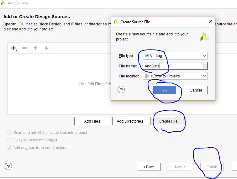
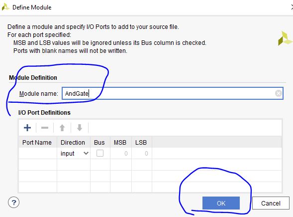
You've created a '.v' file in your project. Your
Vivado may ask you to give a name to the module
in the '.v' file. The .v file and module names can be different. In
this example, let's just call the module 'AndGate' as well. You don't
need to assign I/O port in this step, you can do it later. So leave
them blank, and click 'OK'.
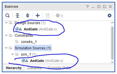
Now, the design file is created. You will see your files
in the
'PROJECT MANAGER'. There are three drop down menus, 'Design Sources',
'Contraints', and 'Simulation Sources'. For this 1st example, we don't
need anything in the 'Contraints' menu. 'Constraints' defines the
pin map of the hardware which is not needed for this simulation
example.
Double click 'AndGate.v' in the 'Design Sources' dropdown menu,
you will see the code editor window on the right hand side.

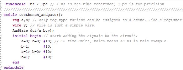
Now, you can type your verilog code in the window:
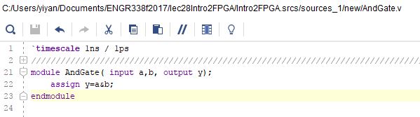
`timescale
1ns/1ps means the time unit is 1 ns and the resolution is 1 ps.
The next step is to verify the logic using simulations. We need a
testbench (a top module) to pack up this 'And Gate'. Just imagine this
module is a real logic gate you used in the lab, they have 2 inputs and
1 output, but no sources and signals. The gate should be conneted to
outside sources to verify the logic.
Now, let's add a testbench for this AndGate. It is the same way as you
add a regular '.v' source, but let's name it as 'testbench_andgate' to
distinguish it from other design files.
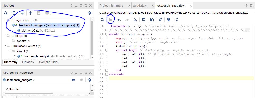
Now you have your testbench added in the source file. But Vivado won't
be able to know this testbench is for your AndGate. After we coded it,
Vivado will automatically detect the hierarchy for these two files, and
make the testbench as the top level layer, and the design file as the
'Device Under Test (DUT)'.
'wire'
elements must be continuously driven by something, and cannot store a
value. Henceforth, they are assigned values using continuous assignment
statements. 'reg'
can be used
to create registers in procedural blocks. Thus, it can store some
value. 'reg'
elements can be
used as output within an actual module declaration. But, 'reg' elements
cannot be connected
to the output port of a module instantiation.
Afer the coding is done, click the 'save' button, the hierarchy will be
updated automatically:
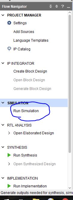
Now, it is ready to simulate the testbench and the DUT.
Click Run Simulation in the 'Flow Navigator'. It will run for several
seconds, then a waveform window will show up. You need to move the
scrollbar to the left to look at your logic. If it is still not
visible, press 'contrl + scroll the mousewheel' to zoom-in or zoom-out
the waveform view.

If
the logic is correct, feel free to turn off the simulation window.
You'll find the window above is 'SIMULATION', not 'PROJECT MANAGER' any
more, so feel free to close it then it will bring you back to 'PROJECT
MANAGER'.
Congratulations, you have completed the first simulation using Verilog
in Vivado. A good start.
Tasks and rubric: (100 points)
1. Install Gvim to your laptop, create a .v file from command line. Make a snapshot of the Gvim window. (50 points)
2.
Install Vivado. Use Gvim to write the AndGate.v file and the testbench
file and run a simulation in Vivado. Make a snapshot of the simulated
results in Vivado. (50 points)