Week 1 Verilog and FPGA Basics
1. Vim Basics
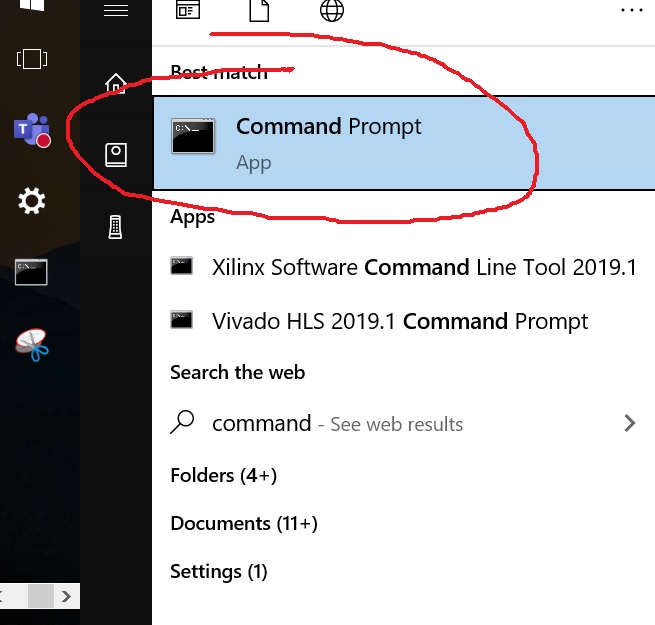
Open gvim from the Command Window
Go through the Vim tutorial here:
http://www.yilectronics.com/Tutorials/vimGit/vimGit.html
Open the command window from the command line:
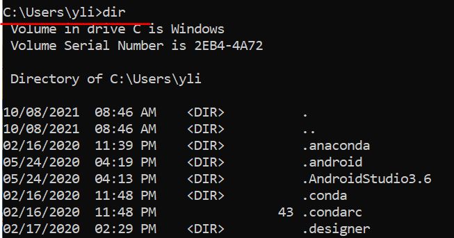
Under the 'Users/YOURNAME/' directory, type 'dir' to show all the files/folders in this directory.
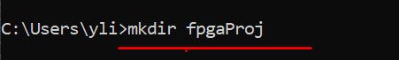
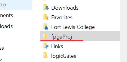
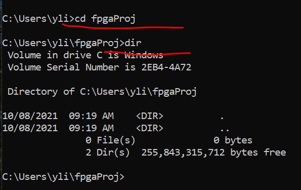
Use 'mkdir fpgaProj' to create a new directory named 'fpgaProj' there.
Use 'cd fpgaProj' to enter the directory, then 'dir' which shows it is empty.
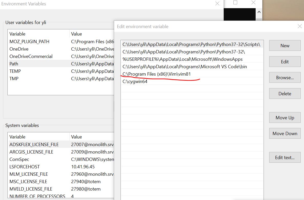
Assume GVIM has been installed to the computer and GVIM's directory has been added to the PATH environmental variable.
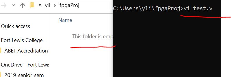
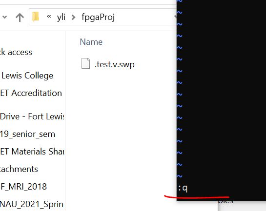
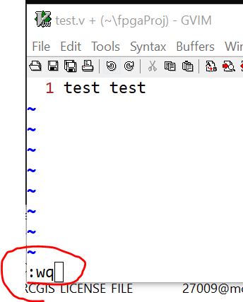
If I type 'vi test.v', a vi editor window will pop up in the command line window.
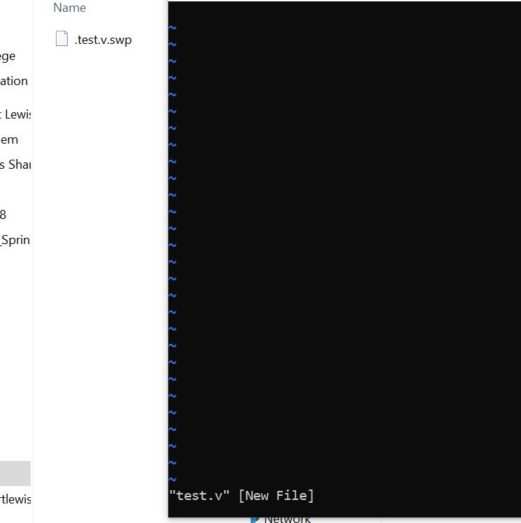
But if I type ':q' but not ':wq' and then press 'Enter', nothing will
be saved and the '.v' file will be deleted in the fpgaProj directory.
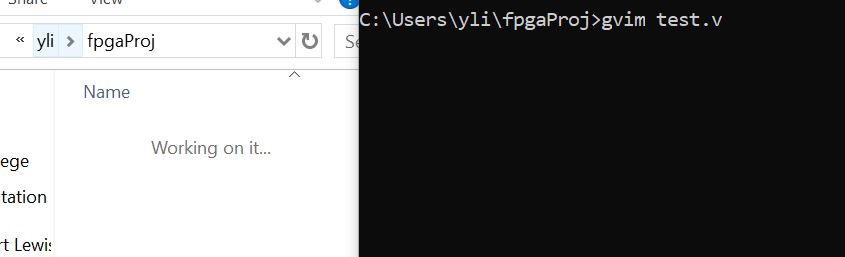
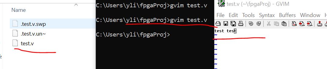
You can also use 'vim test.v' instead of 'vi test.v' to initiate a test
editor but we will use 'gvim test.v' since the interface looks better
than the embedded vi editor.
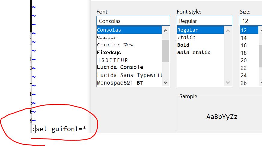
After the gvim window is opened, use 'set guifont=*' to enlarge the
font size: (you don't have to do this if you are ok with the small
font).
Then set line numbers:
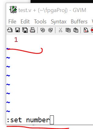
Use ':wq' to write into the file.
You can re-open it using gvim from the command line:
2. Verilog basics
Three modeling methods:
- Structural modeling
- Dataflow modeling
- Behaviroal modeling
Schematic of the example:
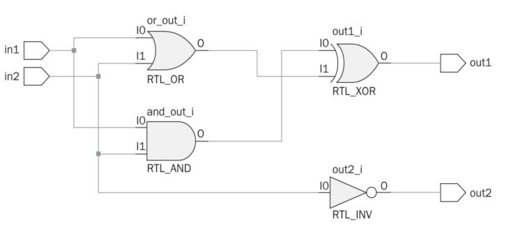
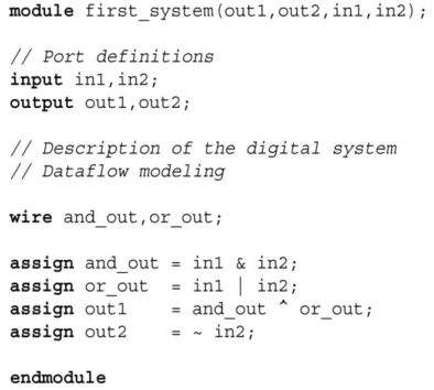
2.1 Structural modeling: (Listing 5.1)
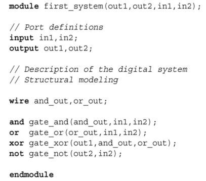
The 'wire' keyword is used for a signal line that is used as both input and output for different blocks.
The order of the arguments do not matter.
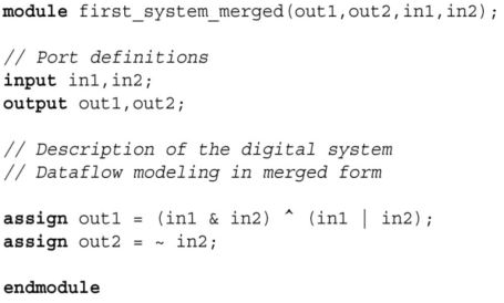
2.2 Dataflow modeling
Uses 'assign output = function of inputs'.
Operators: AND, OR, NOT, XOR: &, |, ~, ^.
Dataflow model of the First System in Merged Form (Listing 5.3)
2.3 Behavioral modeling
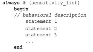
The 'always' block is one of the precedural blocks in Verilog. Statements inside an always block are executed sequentially.
Here, whenever one of the signals in the sensitivity list changes its
state, the behavioral description is executed. Again, order of
statements is not important in behavioral modeling.
Syntax:
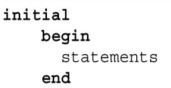
One other important Verilog keyword for behavioral modeling is initial.
Via this keyword, an initial block can be formed which is executed at
time zero. Syntax of the initial block is as follows:
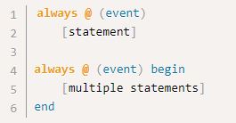
Initial and always statements
describe independent processes, meaning that the statements in one
process execute autonomously. Both types of processes consist of
procedural statements and both start immediately as the simulator is
started. The difference between the two is that initial processes execute once, whereas always process execute repeatedly forever.
However, the assign keyword will not be used in behavioral modeling. Since there is more than one statement to be executed, they are encapsulated within begin and end keywords.
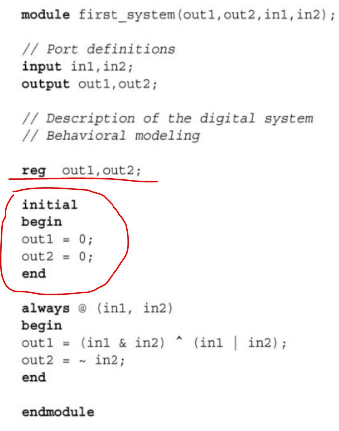
This is a combinational logic block. You can imagine that in1 and in2
are the input pins of a chip, when in1 and in2 changes, out1 and out2
responds to the change. To test the block, you need to connect the chip
to stimuli for in1 and in2.
If there is no change in these variables, output will not be provided by the system. Therefore, we have to save previous output values. This can be done by the Verilog keyword 'reg'.
We used this keyword to keep the previous value of out1 and out2. We
also initialized these variables to logic level zero using the initial
keyword.
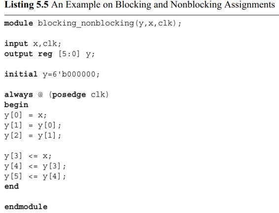
2.4 Blocking and non-blocking in behaviroal modeling.
A good reference that helps you understand blocking and nonblocking assignment better: https://www.nandland.com/articles/blocking-nonblocking-verilog.html
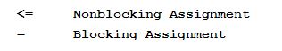
There are two assignment types in behavioral modeling. These are called
blocking and nonblocking. Blocking assignment executes "in series" because a blocking assignment blocks execution of the next statement until it completes.
Therefore the results of the next statement may depend on the first one
being completed. Non-blocking assignment executes in parallel because
it describes assignments that all occur at the same time. The result of
a statement on the 2nd line will not depend on the results of the
statement on the 1st line. Instead, the 2nd line will execute as if the
1st line had not happened yet.
Let’s consider a simple example for blocking and nonblocking
assignments. Assume that there is a Verilog module with output array y
having six elements. Input of the module is represented by x. Within
the always block, let’s describe assignments as follows:
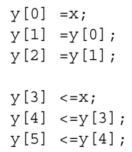
Here, the first three assignments are of blocking type. Next three
assignments are of nonblocking type. When input x becomes logic level
one, blocking assignments result as y[0]=1, y[1]=1, and y[2]=1. In
other words, input first affects output y[0]. Then, outputs affect each
other in sequential order. On the other hand, nonblocking assignments
will be as y[3]=1, y[4]=0, and y[5]=0. Hence, input only affects the
first out-put y[3]. Remaining outputs do not change their initial
value. This is because of the concurrent operation such that all output
values are assigned at once. Hence, the new value of output y[3] could
not affect remaining outputs.
It is strongly suggested in literature that blocking assignments should be used in combinational circuits. Nonblocking assignments should be used in sequential circuits
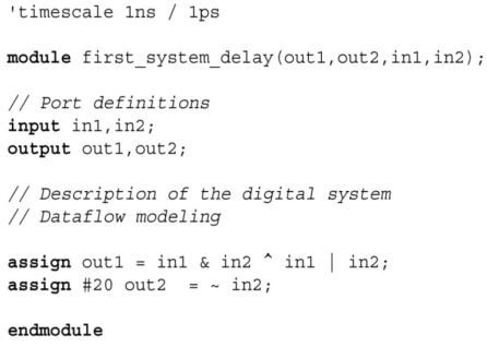
2.5 Timing and delay in modeling
If a blank Verilog file is to be opened, Vivado adds the first line automatically as ’timescale 1ns / 1ps'. These are the default timing values such that the first one (1ns) indicates the reference time unit.
Whenever a time value is added to the Verilog description, it will be
in the order of one nanosecond. The second timing value (1ps) indicates
the smallest precision that can be achieved.
Again, these values will be used during simulation. They will have no effect in the actual FPGA realization step.
Example:
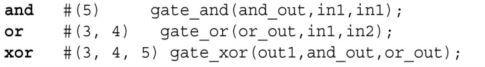
Rise Delay: time needed to logic level one
Fall Delay: time needed to logic level zero
Turn-Off Delay: time needed to high impedence
First one: all types of delay are 5 time units (5 ns here).
Second one: rising delay 3 ns, falling delay 4 ns, turn off delay use the minimum one which is 3 ns.
Third one: rising delay 3 ns, falling delay 4, turn off delay 5 ns.
Example:
assign #10 and_out = in1 & in2
Here, #10 indicates that the assignment will be performed by a 10-time-unit delay.
(Keep
in mind `timescale 1n / 1ps starts with the backtick key on the
keyboard which is the key on the top left corner. That key also has a
tilde on it).
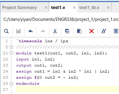
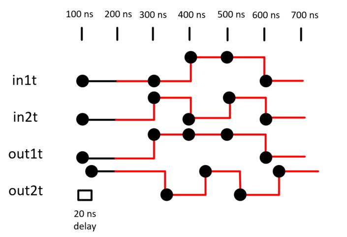
To observe the 20 ns delay, follow the steps shown below:
Write the module file first.
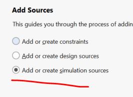
Add a simulation source as a testbench. I used the testbench shown in Listing 4.3.
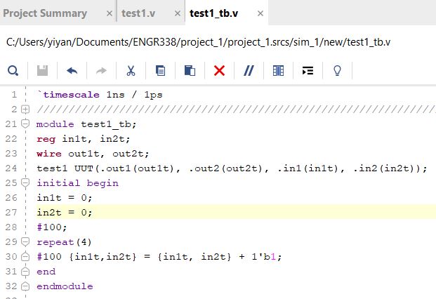
in1t and in2t need to store an initial 0 in each of them so 'reg' is used.
The curely bracket is used to
combine the two variables inside together to form one binary number.
Line 30 is to add a binary 1 to the combined binary number.
Line 28 '#100;' creates a pure 100 ns delay without doing anything.
Line 29/30 is an assignment with a 100 ns delay plugged in in the front. This is repeated for 4 times.
Everything was included in the 'initial begin ..... end' block so it is only being executed once.
In Line 30, make a 100 ns
delay firts, then do the assignment which will plot a point on the
waveform. When it repeats this line again, a 100 ns is applied to it
first and that is why you can see a enlonged voltage level until the
assignment is executed and a new point will be plot on the waveform
again. The following diagram explains test1.v and test1_tb.v:
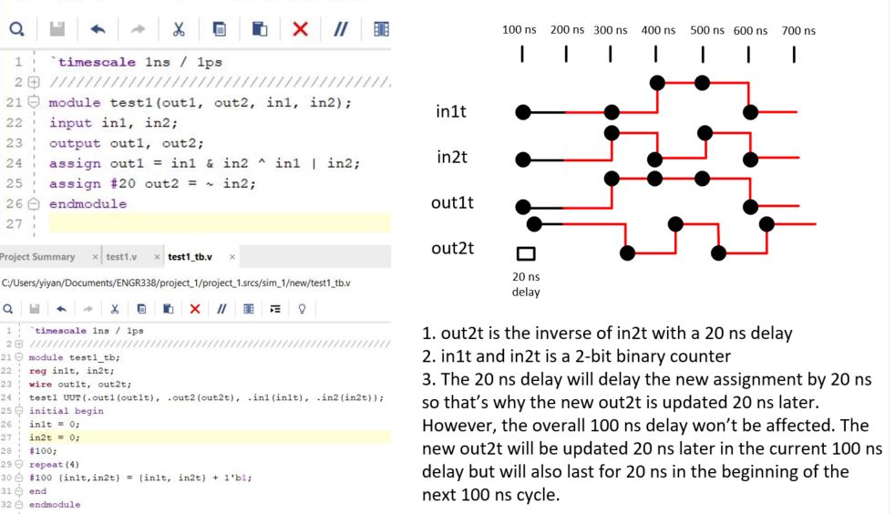
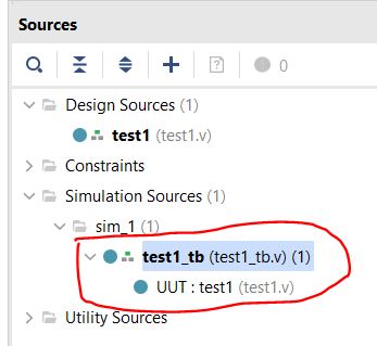
Since the testbench contains the 'test1 UUT' so the test1 module is automatically added to the package at a lower hierarchy.
Then run simulation to show the waveforms.
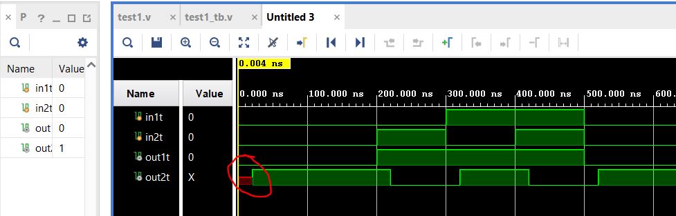
The 20 ns delay is shown in the waveform above.
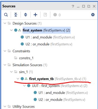
2.6 Hierarchical Module Representation.
Multiple modules at different hierarchies can be included in one '.v' file. Just use different modules to describe them.
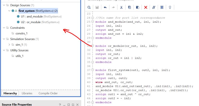
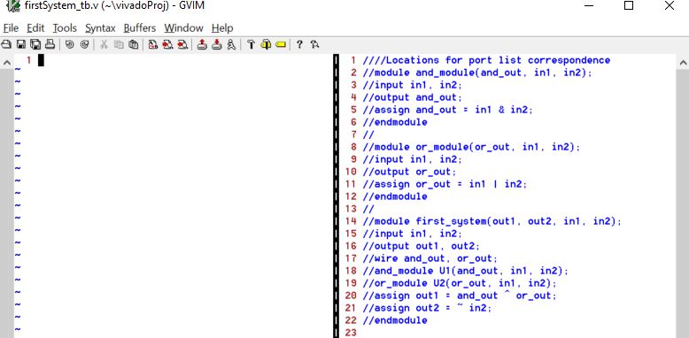
The following example was typed in gvim and added to the project as a design source
Vivado is able to detect the
hierarchy because the 'and_module' and the 'or_module' are instantiated
in the 'first_system' module.
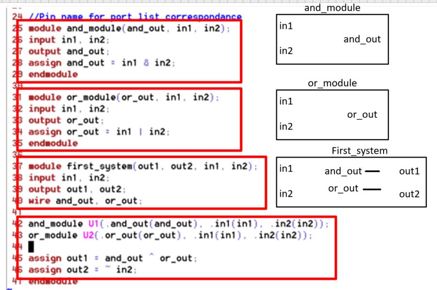
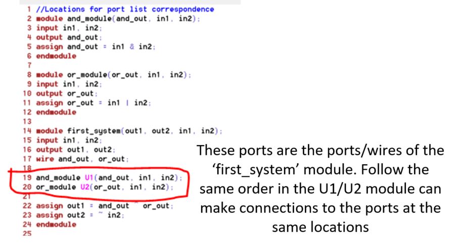
The following diagram may
help clarify the functions of the script. Please note that the ports
claimed in the sub-modules are not shorted together until the
instatiation in the 'first_system' module although the different
modules use the same name 'In1, In2, etc'.
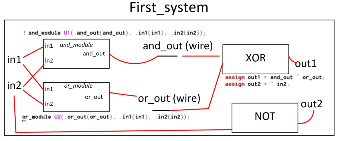
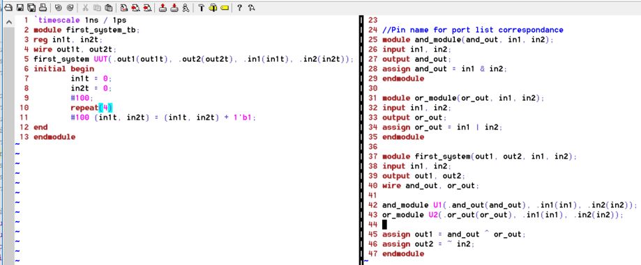
Here is how the connections are made:
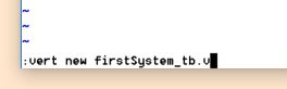
Now, in gvim, use ':vert new first_system_tb.v' to create a new file in a new window aligned aside with the original one.
Type a testbench script in the new window and save it using ':w'.
Add the testbench file as a simulation source to the project.
Run the simulation to verify the logic.
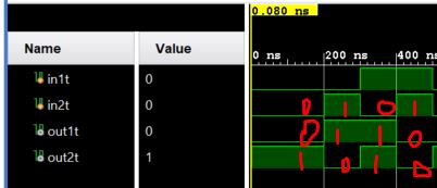
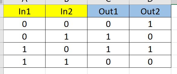
According to the logic, the truth table is as follows:
Out1 = (In1 x In2) ^ (In1 + In2)
Out2 = ~ In2
In addition to the '.port_in_UUT(port_in_tb)' method, connection can be made by the following method as well.
--------------------------
Tasks:
1. Use gvim and Vivado to
simulate the examples in sections 2.1, 2.2, and 2.3. Post snapshots of
gvim windows and vivado simulation results in your report. You must
create testbenches for your simulations. (20 points)
2. Run a simulation to show
the difference between blocking and non-blocking assignment in the
example in section 2.4. (20 points)
3. Repeat the simulation example in section 2.5. (20 points)
4. For the example in section 2.5, move the 20 ns delay from Line 25 to Line 24 and run the simulation. (20 points)
Hand draw the timing diagram on a paper as follows. Take a picture of the drawing and insert to your report as a picture.
5. Use gvim and vivado,
repeat the example in section 2.6. Post the gvim windows and the vivado
simulation windows for credit. (20 points)
** gvim commands:
shift + v - ready to make selection
:norm i// - to comment out code
:norm xx - to remove the // comment slashes
gg - to the top of the file
G - to the bottom of the file
0 - cursor to beginning of line
$ - cursor to end of line
A - cursor to the end of line and edit
y - copy (usually do the V - selection first)
yy - copy a line
p - paste to the next line
:vert new xx.v: to create a new window/file aligned aside. An alternative way to do it - :lefta vsp <filename> - start a file on left, split the window
ctrl + ww - switch between windows
:w - to save without quiting
:wq - to save and quit
:set guifont=* - to set gui font size
:set number - to show line numbers
windows command line window:
rmdir /s <dirname>
mkdir <dirname>
cd ..
cd <dirname>