Zedboard Examples - Build a Follower Interface
(This tutorial was developed by referring to the videos published by ivslab at National Yang Ming Chiao Tung University)
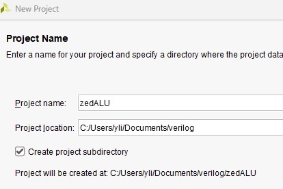
First, create a new project 'zedALU'.
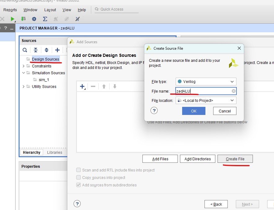
Add source file 'zedALU.v'.
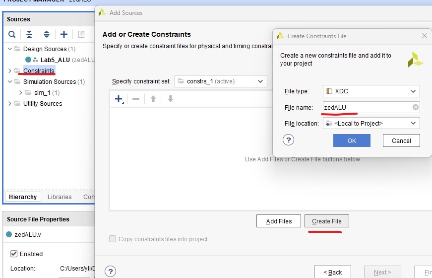
Create constraint file 'zedALU.xdc'.
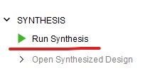
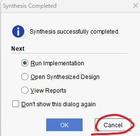
Run synthesis but not implementation.
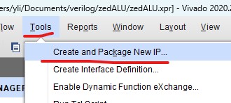
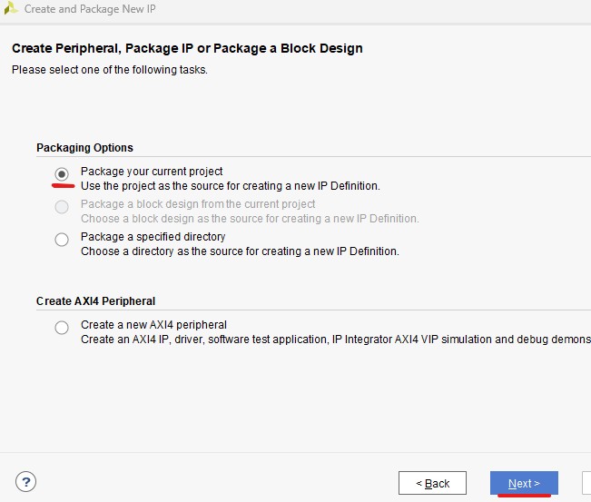
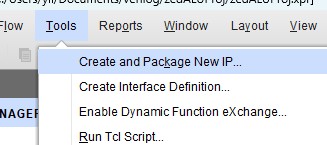
Then create and package new IP.
Then quit Vivado.
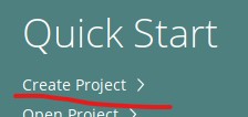
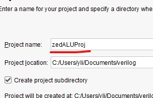
Restart Vivado and create a new project 'zedALUProj'
Select the 'Create new AXI4 peripherals'.

Name it zedALUFollower
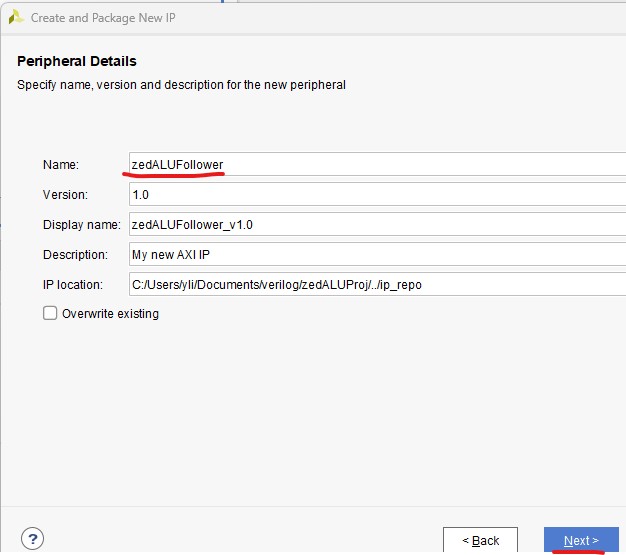
Keep the original settings.

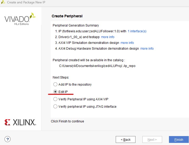
Then select Edit IP.
Replace the verilog in 'zedALUFollower_0' and 'zedALUFollower_v1_0_S00_AXI_inst' with this one and this one respectively.
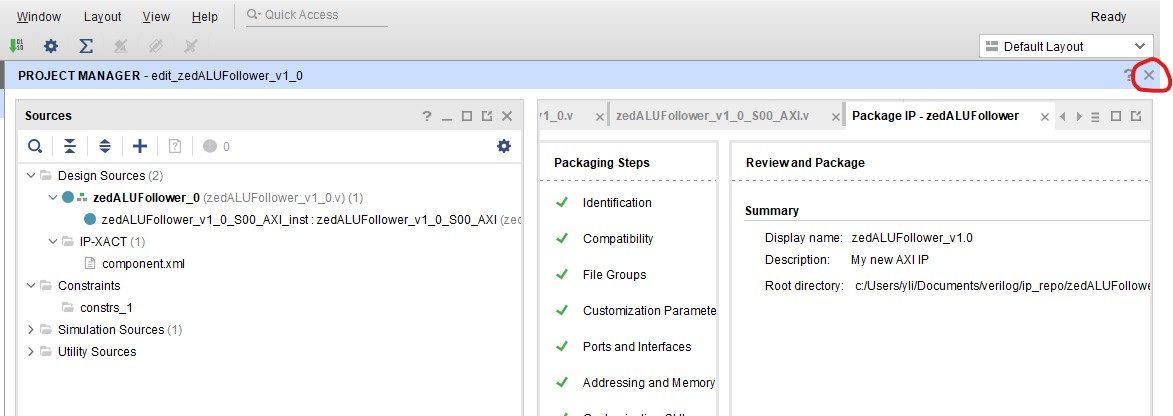
Then on the left hand side of the window, select 'Edit Packaged IP'.

Select Customization Parameters, click 'Merge changes......'

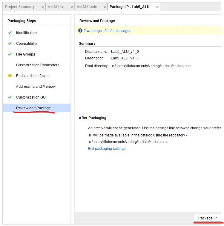
Then click 'Review and Package', and 'Re-Package IP'.

Close it.
Go to Settings.
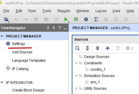
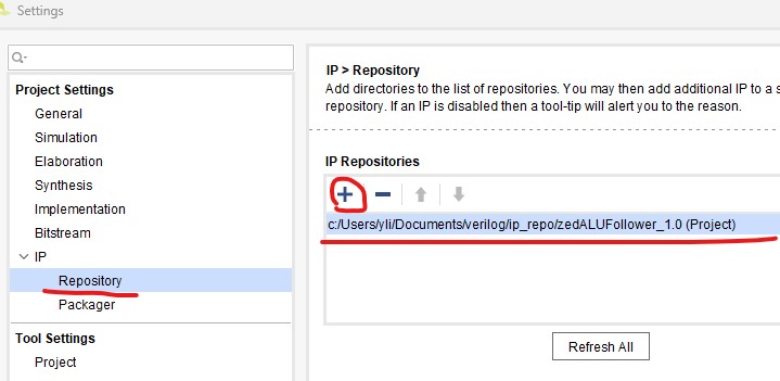
Add the previously created IP 'zedALU' into this project.

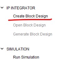
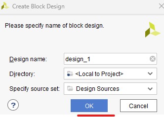
Now add the wrapper.
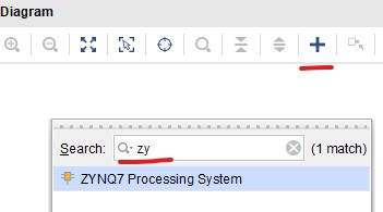
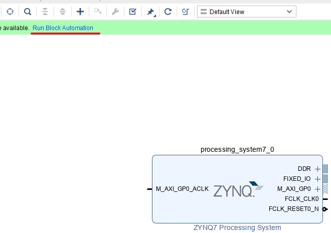
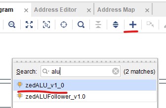
Search and place the core IP.
Click 'Run Block Automation'.
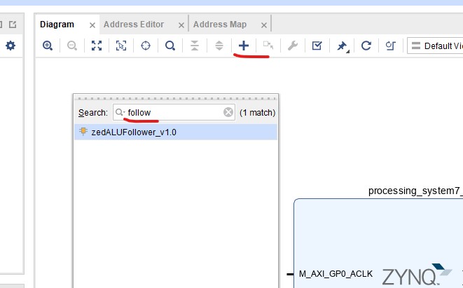
Search and place the Follower module.
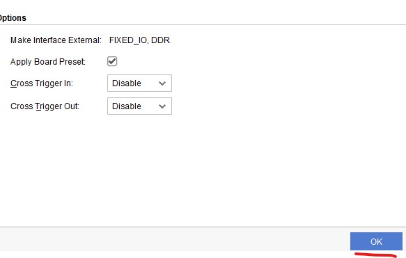
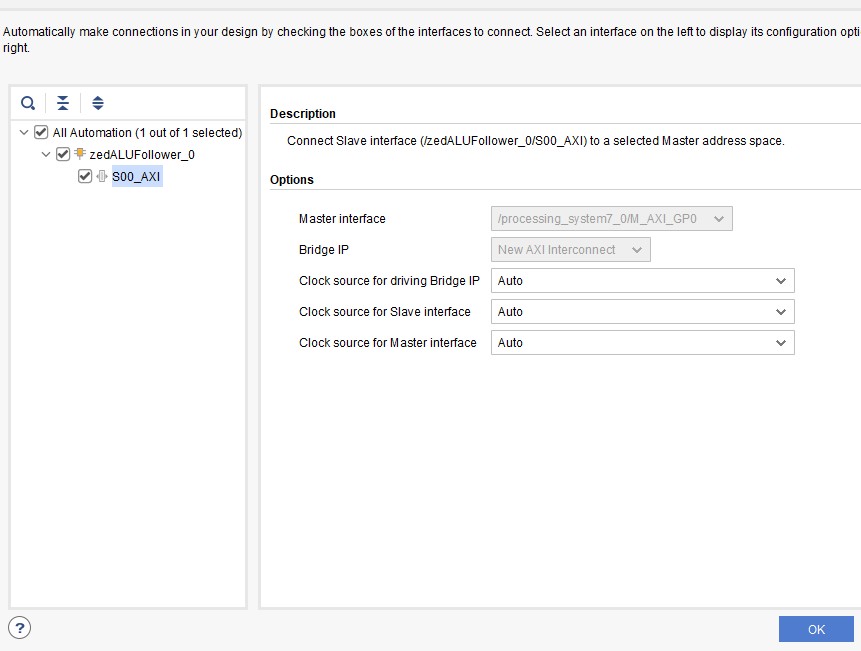
Let Vivado Run the Block Automation.
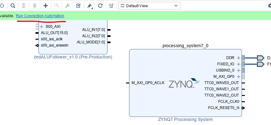
Make sure that 'All Automation' is checked.
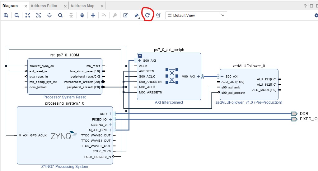
Reshape everything.
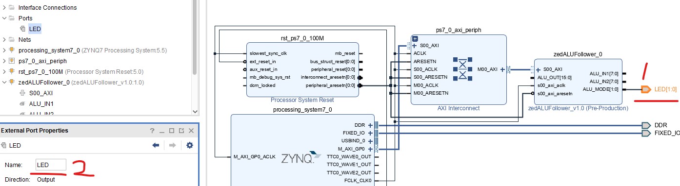
Click 'ALU_MODE{1:0}' external wire
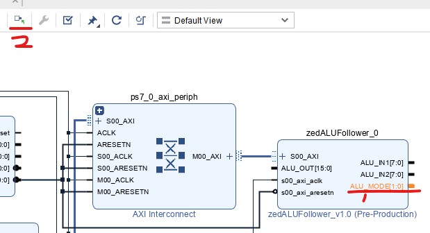
Change its name to 'LED'.
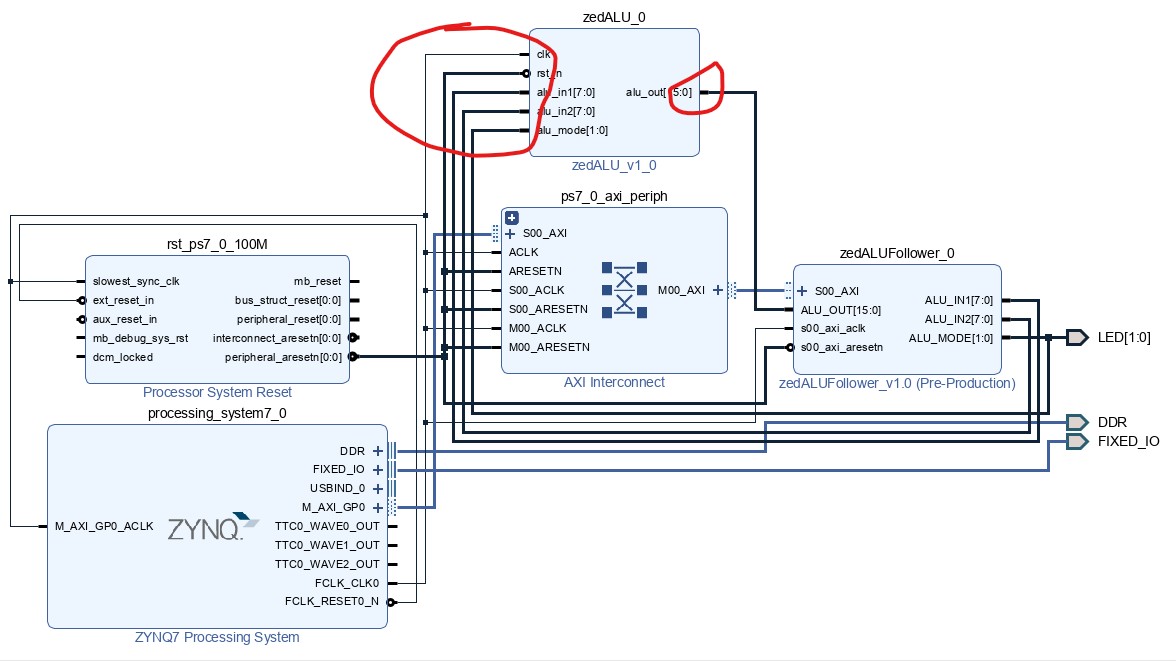
Bring both pieces of code together.
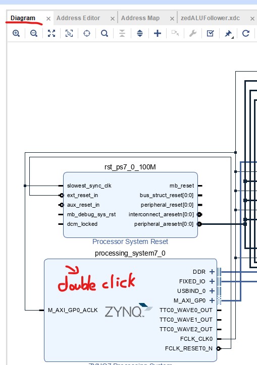
Observe the following diagrams and wire up your design.
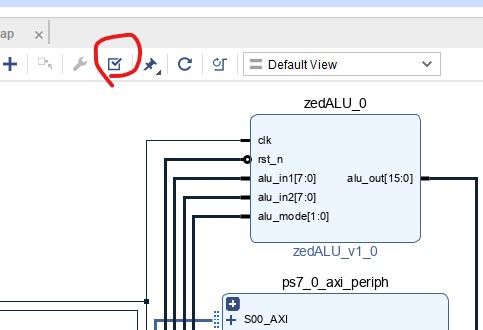
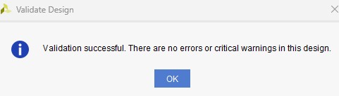
Run 'Validate Design'.
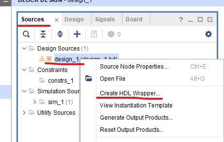
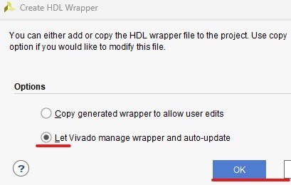
Right click the IP in 'Sources', Click 'Create HDL Wrapper'.
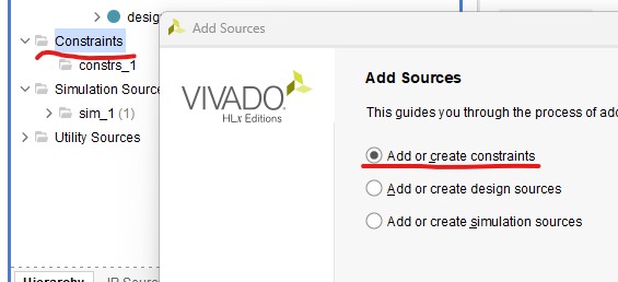
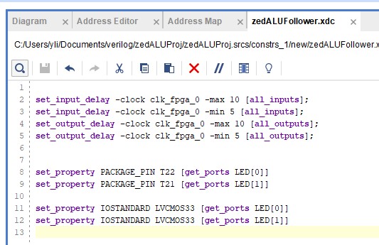
Add a constraint file.
Name it 'zedALUFollower'. Here is the zedALUFollower.xdc' file.
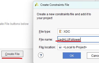
Copy/paste the content into this constraint file.
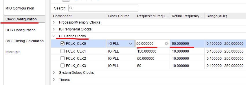
Change the frequency from 100 MHz to 50 MHz since the ALU IP is able to handle only up to 50 MHz.
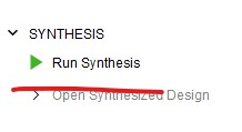
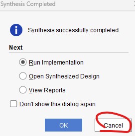
Run Synthesis.
Don't run implementation so cancel the following window.
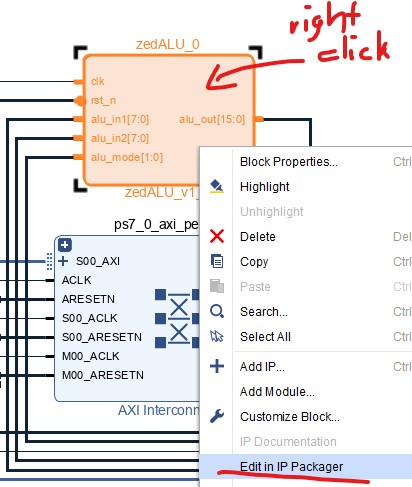
Right click the ALU block in Diagram, select 'Edit in IP Packager'.
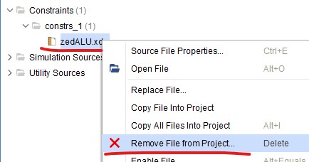
Remove the previous constraint file to avoid conflict.
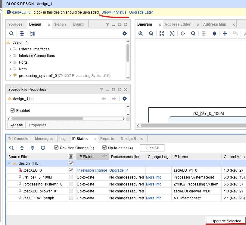
In File Groups, select 'Merge Changes from File Groups Wizard'.


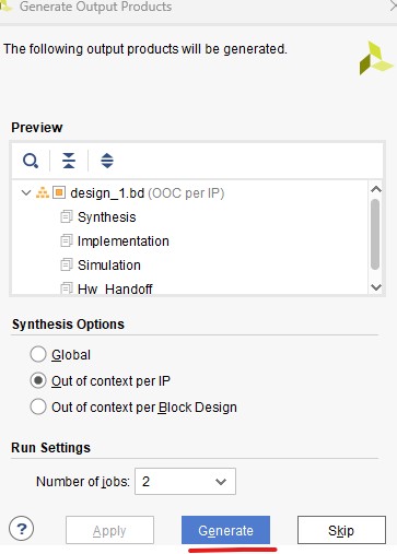
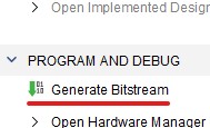
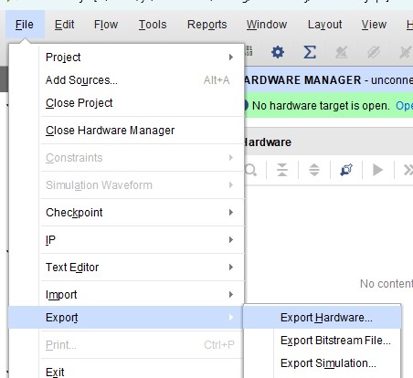
Generate Bitstream.
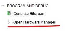
Open Hardware Manager.

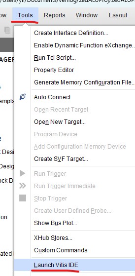
Now open Vitis IDE to program the software.
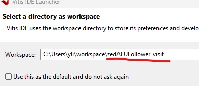
Create
a new folder called 'zedALUFollower_vitis' under the 'workspace'
folder. (Note that don't use the same workspace for different
projects).
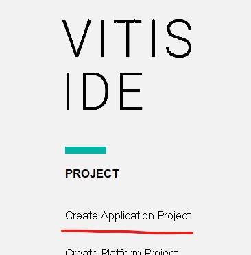
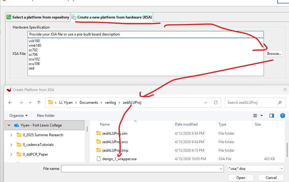
Click 'Create Application Project'.
Browse for the xsa file in your project folder.
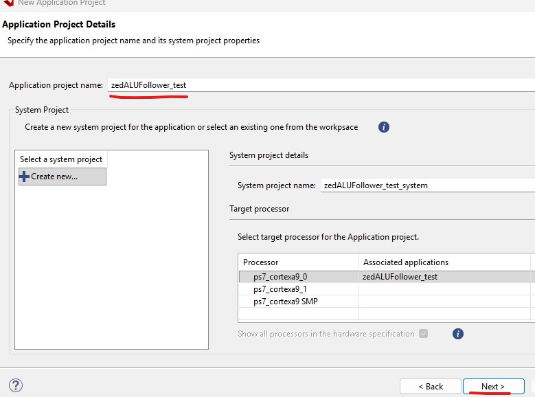
Name the project 'zedALUFollower_test'.
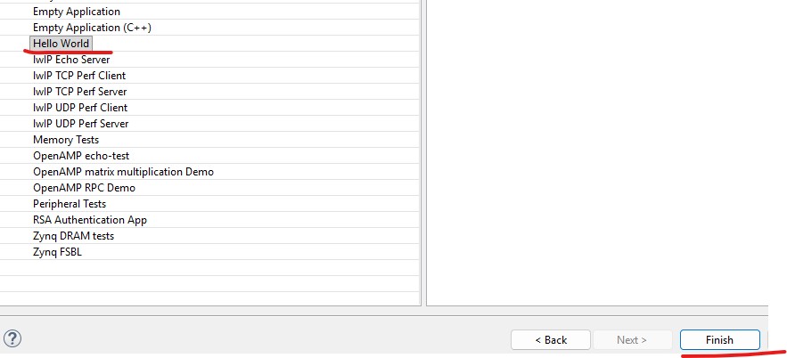
Select the 'Hello World' template.
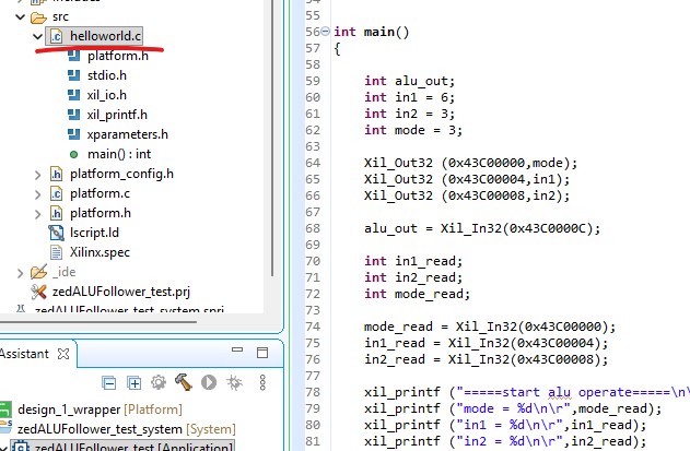
Open the helloworld.c template, replace the code with this new one.
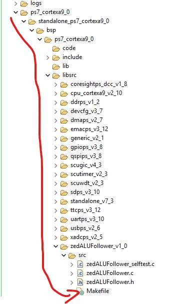
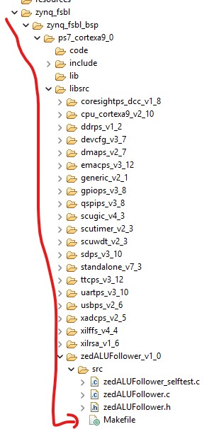
There are three makefiles that needed to be replaced by this new Makefile.

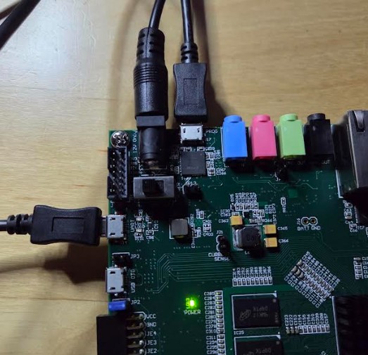
Connect the zedboard to the power supply (12V DC) and two micro USB ports.
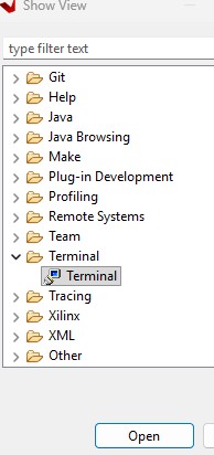
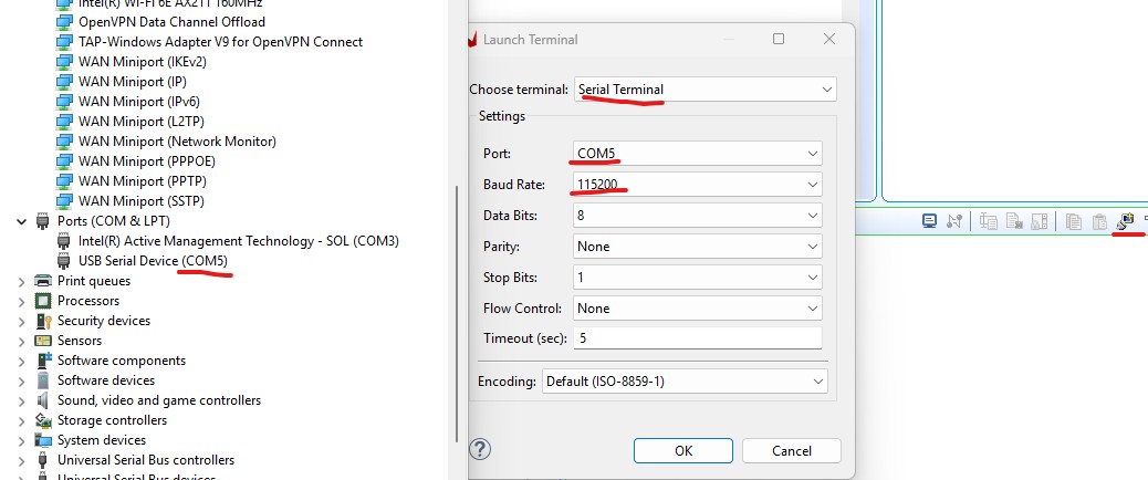
Open the terminal in Vitis.

Make sure the port number and baud rate are correct.
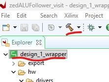
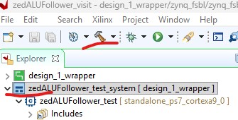
Build the design wrapper adn the system respectively.
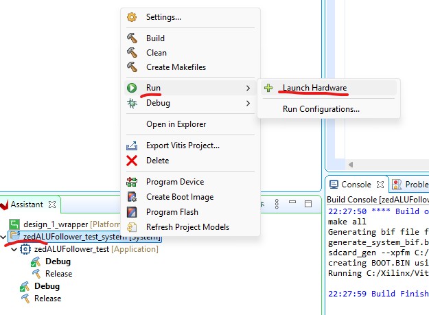
At
the bottom left, in the Assistant tab, right click the system and run
it. Note that only click 'Launch Hardware' once, the next time you run
it, direclty click the created Debug engine instead.
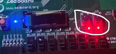
Results should be displayed in the terminal and on the LEDs. Mode 3 is for division and it divides 6 by 3.
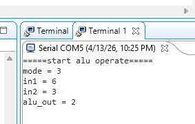
LEDs show the mode it is currently at.

----------------------------------------
Tasks:
Repeat all the steps in this tutorial.