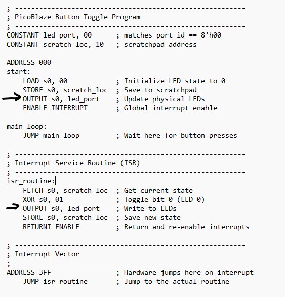
1. Using a pushbutton to trigger the ISR and toggle an LED
To detect the rising edge, the following debouncing circuit is used. When btn_interrupt == btn_clean == 0 at the beginning, it stays at db_count <= 0 and never runs the 'else' part. As
soon as a difference is detected, db_count starts incrementing. However
for vibrations, it may never reach the max count and it will go back to
the first conition and set db_count to 0 again. When the delay is
satisfied, it indicates that the bounces are gone and the signal is
stable so we can give btn_interrupt to btn_clean which is a '1'. Then is repeats this process to output bounce-free square pulses at btn_clean.
// 1. De-bouncer (Ignores noise for ~10ms) // --------------------------------------------------------- reg [19:0] db_count = 0; reg btn_clean = 0; always @(posedge clk) begin if (btn_interrupt == btn_clean) db_count <= 0; else begin db_count <= db_count + 1; if (db_count == 20'd1_000_000) btn_clean <= btn_interrupt; end end
In
the following edge detection code, 'else if (btn_clean &&
!btn_prev)', if the result in the parenthesis is 1 that means btn_clean
is 1 and btn_prev is 0 which defines a rising edge. The PicoBlaze
has a dedicated interrupt_ack signal. Once the processor starts its
Interrupt Service Routine (ISR), it sends this "handshake" signal back.
The code then resets interrupt_reg to 0 so the processor isn't
interrupted repeatedly for the same single press.
In this logic,
the handshake ensures that a single event (like a button press) is
captured reliably and processed exactly once. Think of it as a
three-step relay: Request (The Button): Your external logic (the
btn_clean rising edge) sets interrupt_reg to 1. This is your hardware
saying, "Hey, something happened!" Acknowledgment (The CPU): The
PicoBlaze processor samples its interrupt input every two clock cycles.
Once it detects the 1, it saves its state, jumps to the Interrupt
Service Routine (ISR), and pulses its interrupt_ack output pin. This is
the CPU saying, "I got your message, I'm handling it now." Clear
(The Logic): Your code sees the interrupt_ack signal and immediately
resets interrupt_reg back to 0. This is your hardware saying, "Great,
I'll put the sign down so I don't bother you again until the next
button press."
Why this specific order matters: If you didn't have Step 2 (ACK): You might clear the signal before the CPU even saw it, and the button press would be ignored. If
you didn't have Step 3 (Clear): The CPU would finish the ISR, see that
the interrupt signal is still high, and immediately start the ISR
again—trapping your program in a loop forever.
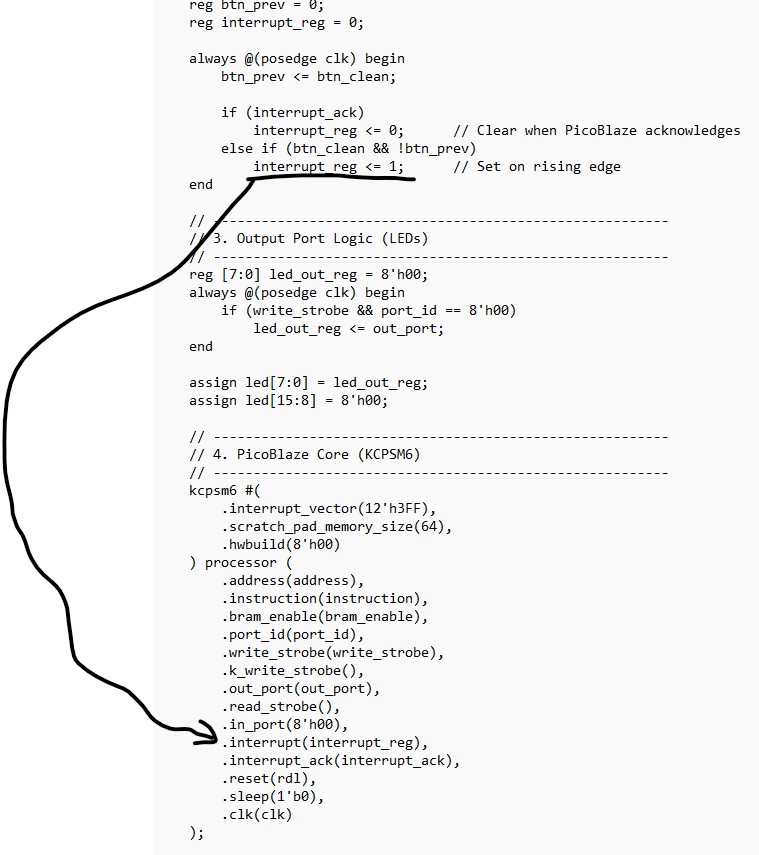
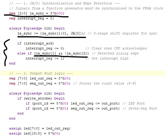
// --------------------------------------------------------- // 2. Edge Detection & Interrupt Handshake // --------------------------------------------------------- reg btn_prev = 0; reg interrupt_reg = 0; always @(posedge clk) begin btn_prev <= btn_clean; if (interrupt_ack)
interrupt_reg <= 0; // Clear when
PicoBlaze acknowledges else if (btn_clean && !btn_prev)
interrupt_reg <= 1; // Set on rising
edge end
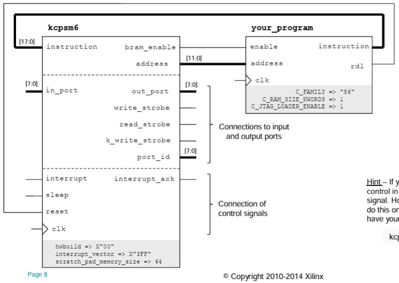
The
PicoBlaze interrupt pin acts as an external signal to force the
processor to pause its current task and jump to a special interrupt
service routine (ISR). The interrupt_ack (Interrupt Acknowledge) pin is
an output signal from the processor confirming that the interrupt has
been accepted, allowing external hardware to reset the interrupt
request.
Interrupt
Input Pin: When driven high (logic '1'), the processor finishes its
current instruction, saves the program counter and flags, and jumps to
a predefined vector address (default is 3FF hex). Interrupt_ack
Output Pin: Used to inform external hardware that the interrupt request
is being serviced. This pin goes high during the RETURNI instruction in
the ISR to signal the external device to lower its interrupt signal. Purpose:
These pins allow the PicoBlaze to react to asynchronous events (like
button presses or timer timeouts) in the FPGA fabric without constantly
polling for status changes.
PicoBlaze (KCPSM6) clears the interrupt_ack pin by itself. The
interrupt_ack signal is a single clock cycle pulse. It is automatically
generated by the processor's internal state machine at the moment it
recognizes the interrupt and begins the transition to the interrupt
vector.
How the Pulse Works Trigger: When the interrupt input is driven High and interrupts are enabled, PicoBlaze detects the signal. Acknowledgment: The processor immediately drives the interrupt_ack pin High for exactly one clock cycle. Automatic
Clear: After that single clock cycle, PicoBlaze automatically returns
the interrupt_ack pin to Low ('0') without requiring any specific
instruction in your code
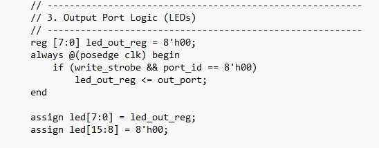
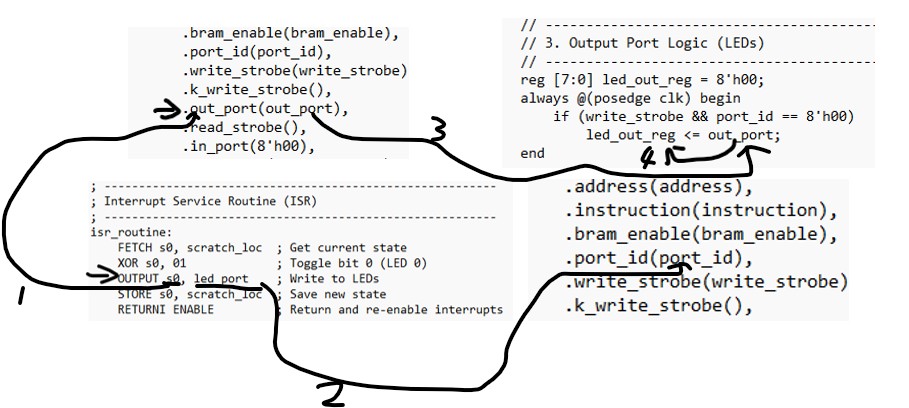
if (write_strobe && port_id == 8'h00) This condition acts as an address decoder and write enabler. write_strobe: A signal that indicates a write operation is occurring. port_id == 8'h00: Checks if the target address (port) is 00. &&: Both conditions must be true. The register only updates if a write is enabled and the address matches port 00.
The instruction that makes write_strobe true is OUTPUT. In PicoBlaze architecture, the OUTPUT instruction performs two simultaneous hardware actions: It places the value of a register (like s0) onto the out_port bus. It
asserts the write_strobe signal for exactly one clock cycle to tell the
external hardware (your led_out_reg) to capture that data.
Registers
( through ): These are high-speed storage locations inside the CPU
itself. The processor uses them directly to perform math or logic (like
your XOR and LOAD commands). They are the "workspace." Memory
(Scratchpad): This is a separate storage area (accessed with STORE and
FETCH). It is slower than registers but holds more data.
LOAD s0, 00: You are putting data into a register to work on it. STORE s0, scratch_loc: You are moving that data out of the CPU and into memory for safekeeping.
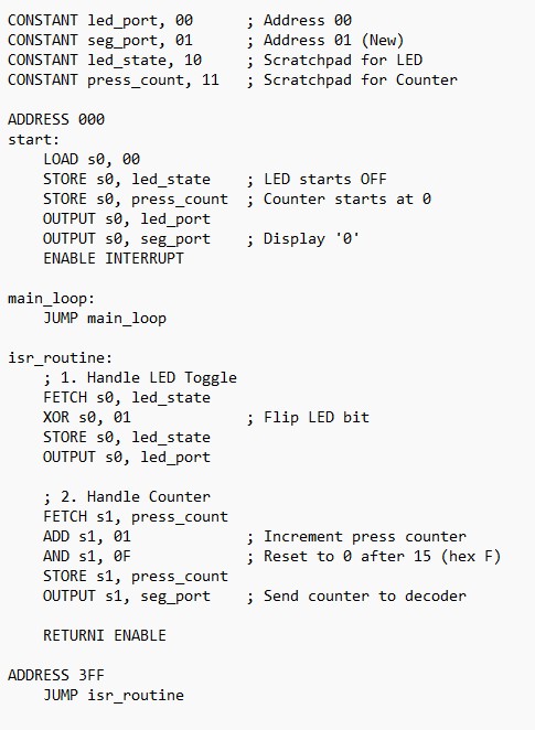
RETURNI
stands for Return from Interrupt. It’s a specialized command used
specifically at the end of an Interrupt Service Routine (ISR) like the
one in your code. When a PicoBlaze processor handles an interrupt, it
automatically "locks the door" (disables interrupts) so a second
interrupt doesn't crash the first one. RETURNI is the proper way to
"unlock the door" and go back home in a single step.
When the PicoBlaze reaches the instruction OUTPUT s0, led_port: Data: It puts the value of register s0 (e.g., 8'h00) onto the wires named out_port. Address: It puts the value of led_port (defined as 00) onto the wires named port_id. The "Now!" Signal: It flips a switch called write_strobe to High (1) for exactly one clock cycle.
Note
that '.port_id(port_id)' leaves the wire port_id a variable. The
assembly code line 'OUTPUT s0, led_port', the 'led_port' defines the
port_id for this write operation.
This applies to applications where the output is connected to different ports. The code could be written as:
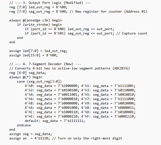
always @(posedge clk) begin if (write_strobe) begin if (port_id == 8'h00) led_out_reg <= out_port; if (port_id == 8'h01) seven_seg_reg <= out_port; // Logic to load it end end
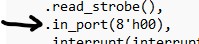
For
the '.in_port(8'h00)' connection, .in_port(8'h00) is "shorted" to
zero because this particular program doesn't need to read any external
data. Here is the breakdown of why it was designed that way: 1. It relies on Interrupts, not Polling In
many programs, the CPU constantly "polls" (checks) a button by reading
an input port. However, this code uses the Interrupt system: The hardware (your Verilog edge detector) "pokes" the PicoBlaze using the interrupt pin. The PicoBlaze immediately jumps to the isr_routine. Because
the interrupt already told the CPU that the button was pressed, the CPU
doesn't need to actually "read" the button's state via an input port. 2. Avoiding "Floating" Inputs In
digital logic, you never want an input pin to be "floating"
(disconnected). If you aren't using the input feature of the PicoBlaze,
you must tie it to a constant value (like 00) to ensure the processor
doesn't read random electrical noise if an INPUT instruction is
accidentally executed. 3. Simplicity Since
the only goal of this specific code is to toggle an LED based on a
button press, and that button press is handled by the interrupt logic,
adding an input multiplexer would just add unnecessary complexity to
the Verilog.
2. Count the button press events using the seven segment display modules
The major adition to the verilog code is:
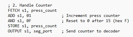
To handle the counting, the following code needs to be included in your assembly:
3. Using an external pulse to trigger ISR and count the rising edges
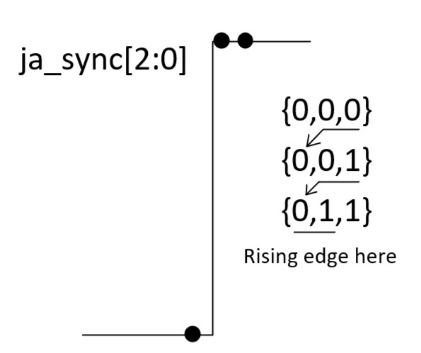
Create a 3-bit vector to store the JA[0] values.
Here is the assembly code:
Tasks: 1. Repeat the work in Section 1 to toggle one LED by pressing a button and trigger the ISR. Show video demos (10 points). 2.
Count the button press events and display it on the seven segment
diaplay module (counts from 0 to 15 then resets to 0). The counting
must happen in the ISR. Show video demos (20 points) 3.
Count 0.5 Hz 0-3.3V function generator rising edges through JA[0]
and diaply the counts on the seven segment display module. Show
video demos (20 points)