Tutorial 3
- Video Streaming Web Server and Robot Car (Module 4 on Rui's textbook)
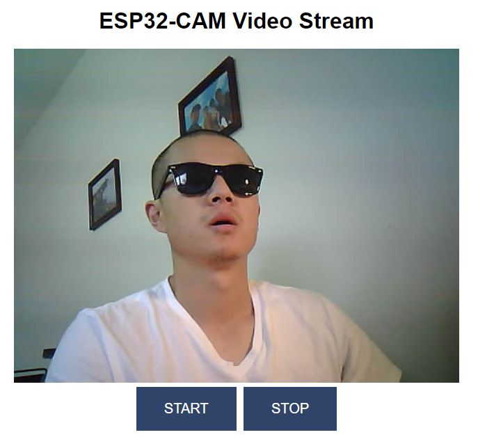
1. Start and stop video streaming on a web server (Module 4 Unit 1)(10 points)
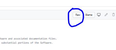
Use the code provided by the textbook. Go to the Github page, click
'Raw' to show the code on a webpage and then copy all over to your IDE
to avoid the empty lines in the sketch.
The code works very well.
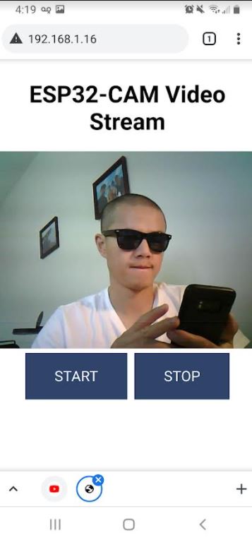
And YES, you can stream it on your phone as well.
2. Video streaming with sensor readings (Module 4 Unit 2)(10 points)
The sensor we have is BMP180 but not BME280, which is used in the textbook's example.
The hardware connection is the same though.
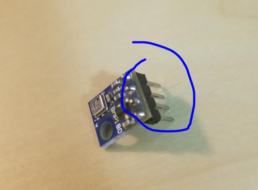
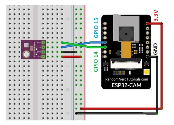
Solder the pin headers to the BMP180 module and then make the hardware connections as indicated in the textbook on Page 272.
(From Rui's textbook)
For the software part, most of the code provided in the textbook is a
good start, you need to modify it for your BMP180. Some hints for this
task:
- In library manager, find 'Adafruit_BMP085' and install it to your IDE.
- Find some example code for BMP180 and ESP32 so you will know the functions and how to read from the sensor. Here is one example code. The link to this code is here.
Please note that it is for a standard ESP32 but not your ESP32-CAM.
Also, in this online tutorial, the ESP32 board is different from the
ones in our lab. The location of SDA and SDL are different.
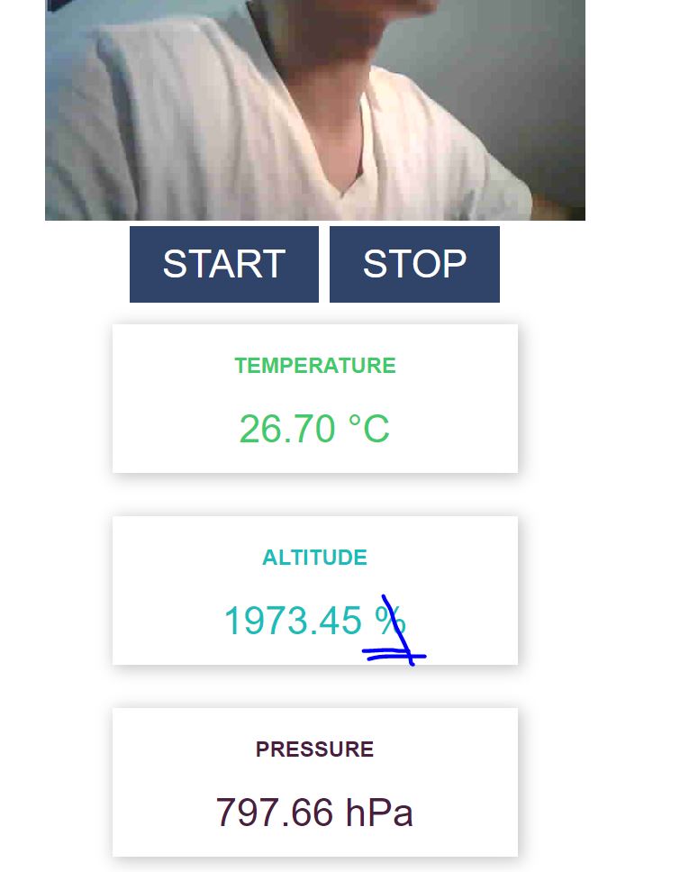
- The BMP180 doesn't have a humidity sensor in it. I chose to display
the altitude instead. You need to make changes to a few places in the
sketch.
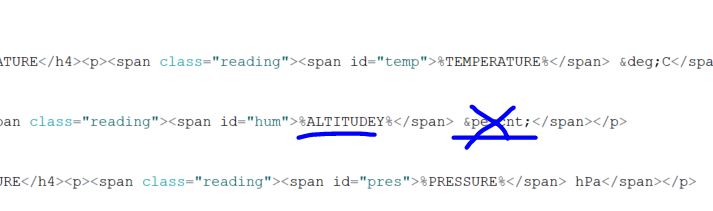
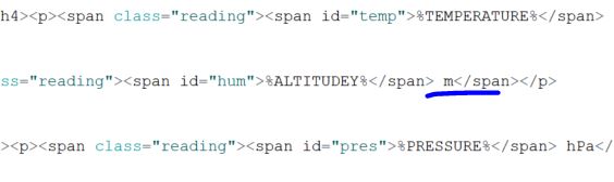
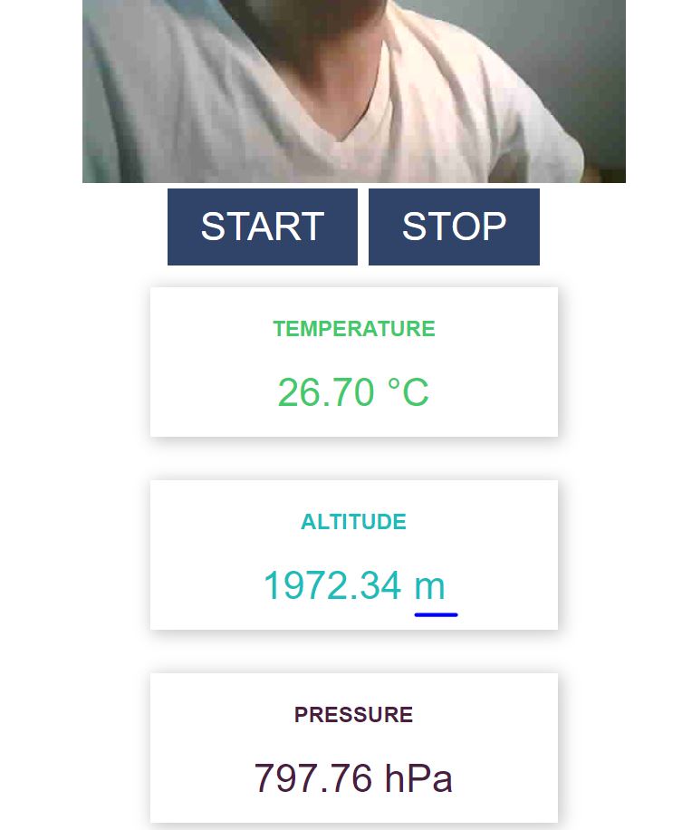
- To remove the '%' sign on the button in the browser, you need to replace '%' with ' m' in the HTML script.
Before removing it:
After:
- It takes a few seconds to show the altitude in the browser so be
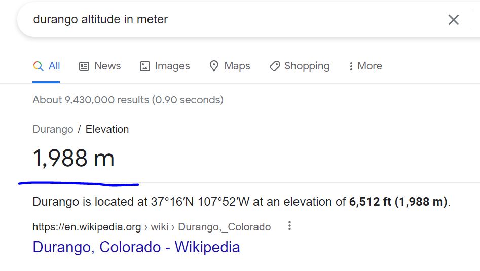
patient. From the altitude read above, it is pretty accurate for
Durango.
Here is the Durango altitude from google:
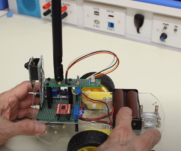
3. Remote controlled car robot with a camera (Module 4 Unit 4)(30 points)
(a snapshot from the YouTube channel DroneBot Workshop)
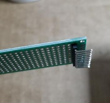
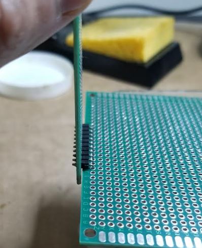
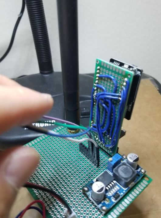
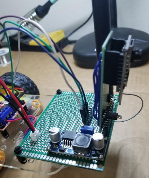
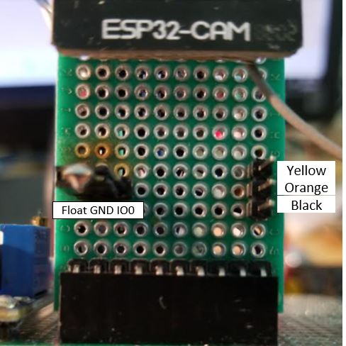
Plan the layout of the PCB and the car first. The following PCB will be
used to mount the ESP32-CAM in the front of the car. Use a 90 degree
header pin strip at one end of the board.
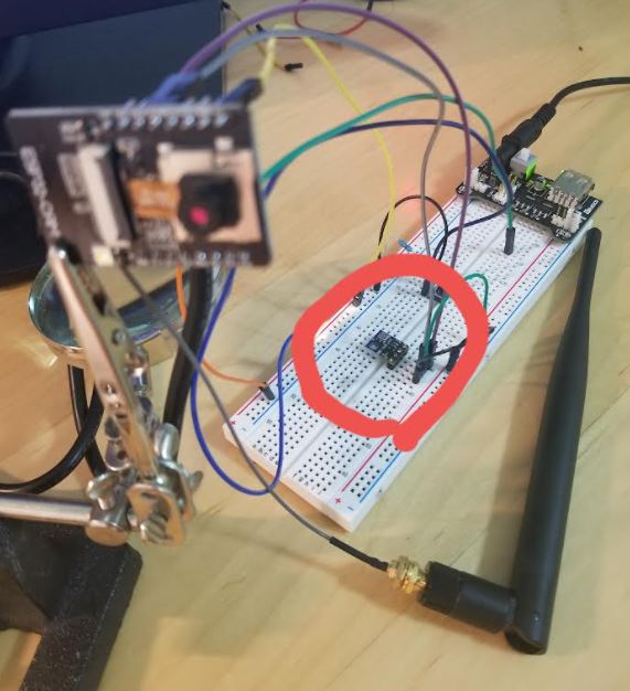
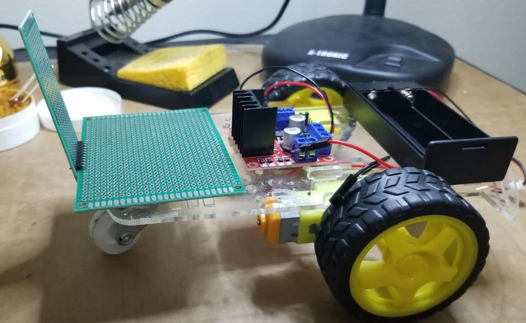
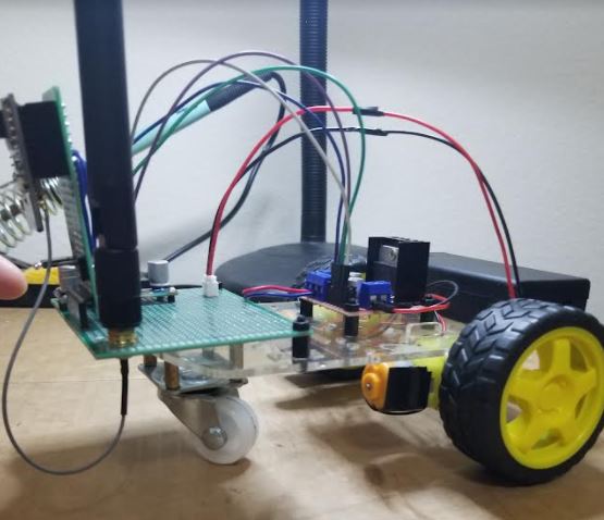
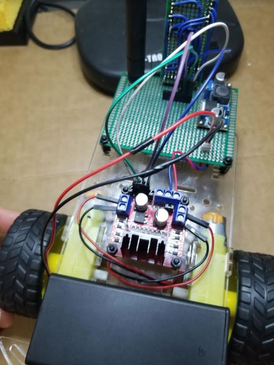
I placed the boards, the driver, and the battery cartridge on the car.
The following photo shows the layout of the components on the car.
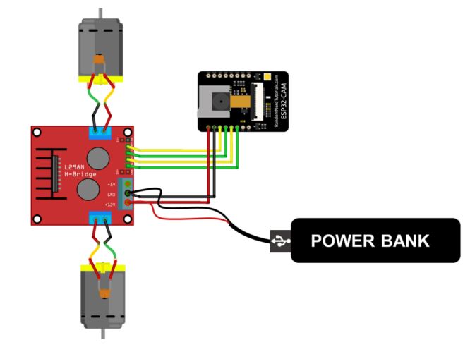
Before you start soldering, you need to know the big picture of all the connections. The following things you need to consider: - The ESP has 4 GPIO pins to control the driver - The ESP needs to be programmed so the PCB need to have an option for the user to short GPIO 0 to GND - There should be three pin headers for the FTDI pins - The rechargeable battery we
have is 7.4 V, it will be directly shorted to the 12 V input on the
driver's PCB. It will also be regularted by the LM2596 module to
generate the 5V for ESP.
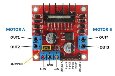
The two critical hardware connections from the textbook:
I only changed the photo quality to '40' and the WiFi credential in the original code on Page 306. It works pretty well. A quick demonstration video:
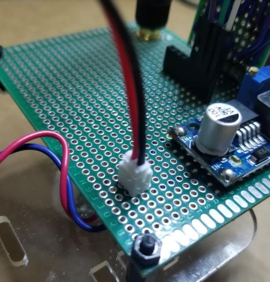
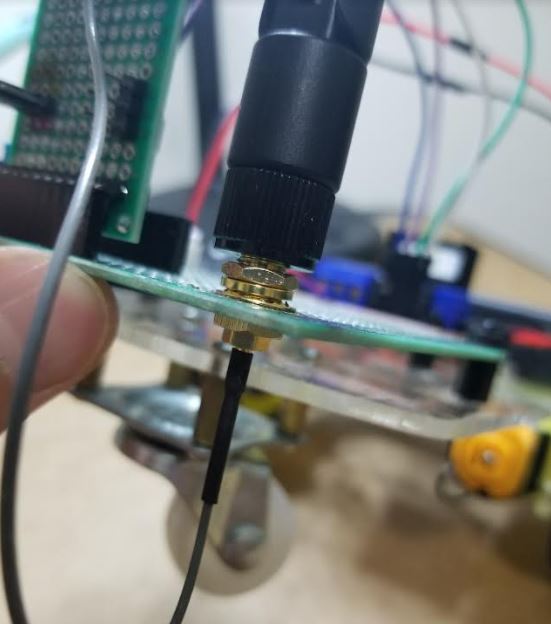
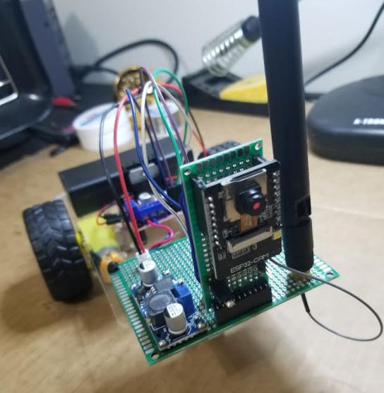
These are some of the photos of my car:
To reprogram it, I must move the jumpers. They are designed as follows:
Reprogram it to change the WiFi credentials if the robot works in a differnet WiFi network.
You must revise the code to rotate the image by 90 degrees to have a upright view of the scene.
4. Design a PCB in Eagle to replace the prototype PCBs that hold the ESP
and the voltage regulator. Don't re-design the PCB for the motor
driver. Solder the PCB and test the functionality. (30 points)