Task
1: Press a button to start blinking an LED (20 points)
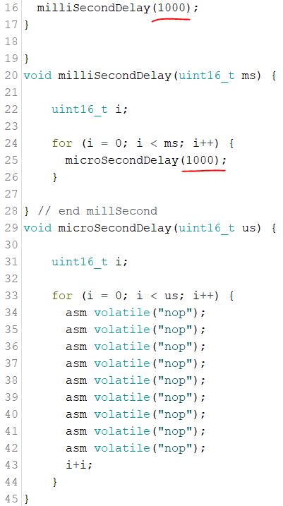
Create a new Arduino sketch, save it. Copy and paste the
following code into your sketch. task1_buttonBlink.txt
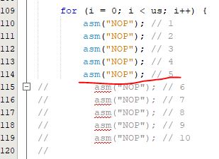
You may have
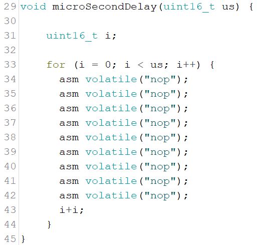
noticed in the code that the delay is created by the nop function. (no
operation but just wastes some time).
Let's assume 10
NOP functions will create a 1 us delay. NOP is an assembly instruction.
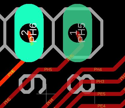
From the Mega
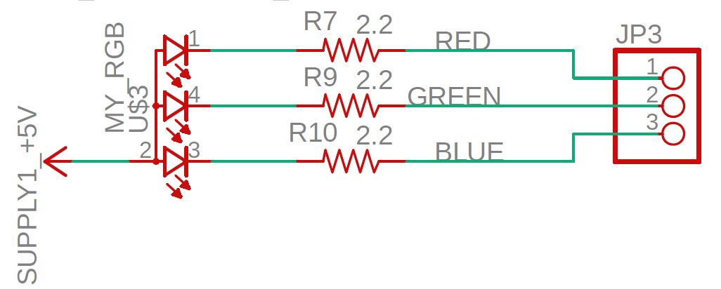
board layout, you can tell that PH6 is Pin 9, PH5 is Pin 8.
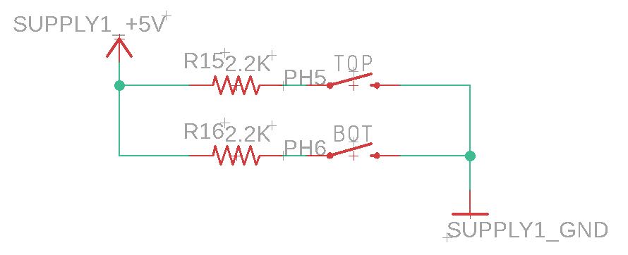
From the Skyboard, you can see that PH5 and PH6 are used for the buttons.
However,
RE5 (Pin3) is not physicall connected to any of the LEDs. you must use
a jump
wire to make the connection. It could be any one of the R, G, or B LED on the board.
Download
the code to your Skyboard and record a video demo of the blinking
LED on the board.
Task
2: Find the number of NOPs for accurate time delay (20 points)
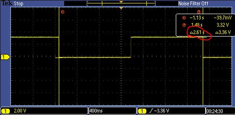
Unplug the
jumper wire that connects the LED and Pin3, then probe Pin3.
I
was assuming 10 NOPs is 1us. Therefore, I used 1000 milisecond x 1000
us in the code to create a 1 s half period to toggle the LED once.
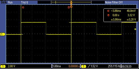
However, from
the oscilloscope, it is longer than 1s - about 2.61s/2 = 1.305s.
Now, let's fix
it to make it more accurate.
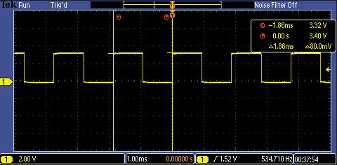
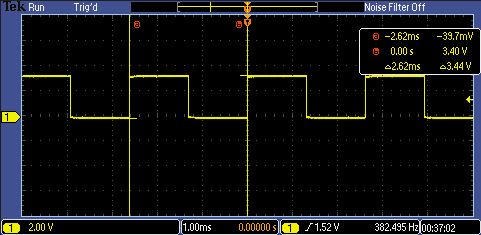
First, make it
faster for a better resolution. Change it to milliSecondDelay(1) and
microSecondDelay(1000).
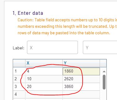
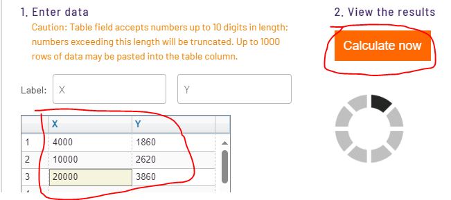
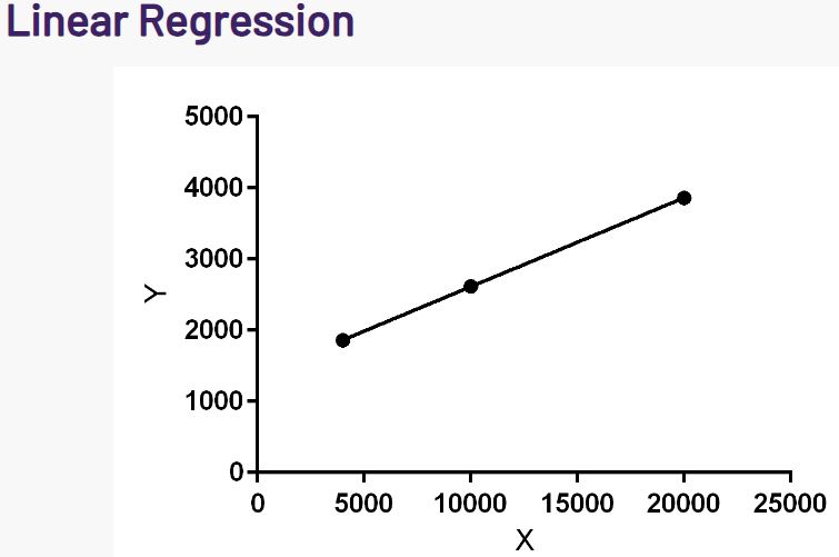
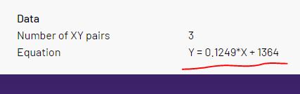
Let's
plug in Y = 2000 us into the equation (for 1000 us per toggling). We
are getting x = 5092 NOPs, so it is about 5 NOPs for 1 us delay. (Your
result could be different since this result was from a different MCU
platform).
Modify the
number of 'NOP's to achieve a 1 s time delay for the LED.
Task
3. The Morse code (40 points)
You will create a program that outputs a sequence of
illumination pulses that transmits a Morse code coded message when
upper
button is pressed. Morse code is a method for transmitting text-based
messages using a series of short and long signals called dot and dash
respectively. The signal, in our case, will be an LED that illuminates
for a short or long period. The pulses of LED illumination are
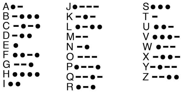
separated by non-illuminated periods of variable length. Each letter
and number has a specific, predefined, pattern of dots and dashes given
in the figure below.
For example in
order to send the message "sos help", your program would flash the LED
in the following sequence:
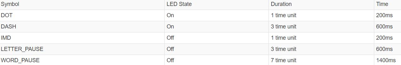
The
sequence "DOT DOT DOT" is code for the letter "s", "DASH DASH DASH" the
code for "o". Everywhere there is a DOT in this message your LED would
be on for 1 time unit, everywhere there is a DASH the LED would be on
for 3 time units. Between the DOTs and DASHes is an the intra-mark
delay (IMD). During the IMD the LED must be turned off for 1 time unit.
Between the letters of the message, a "LETTER_PAUSE", the LED is turned
off for 3 time units. Between the words of a message, a "WORD_PAUSE",
the LED is turned off for 7 time units. We will standardize a time unit
as a fifth of a second or 200 ms.
Here is the code template to start with. Here is the demonstration: (20 points)
Connect PIN 2 to the input pin of the audio amplifier on the board to hear an audio version of the Morse Code. (10 points)
Set up an oscillation at 100 Hz for the tone() and noTone() function as the input to the audio amplifier to make it louder. (10 points)