To
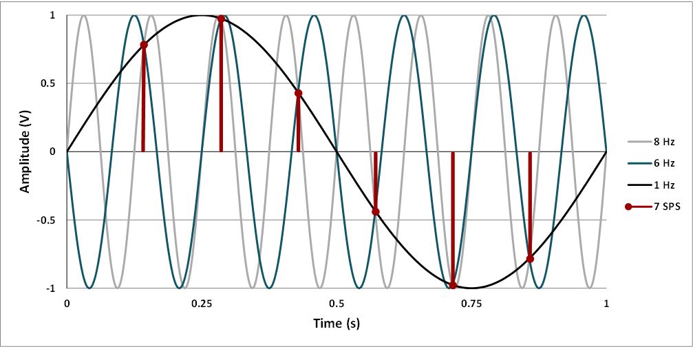
avoid aliasing, the sampling frequency of an Analog-to-Digital
Converter (ADC) must be at least twice the highest frequency component
of the analog signal you are trying to digitize. This is known as the
Nyquist theorem, and the minimum sampling rate is the Nyquist rate. In
practice, it is recommended to use a sampling rate that is
significantly higher than the minimum and to use a low-pass filter
(anti-aliasing filter) before the ADC to remove frequencies above half
the sampling rate.
If you sample a voltage through an ISR, the frequency the code gets into the ISR will be the sampling frequency. The
best practice is to use the ADC Conversion Complete ISR. When the ADC
conversion is completed, it interrupts and you can process and store
the data inside the ISR. This keeps the code organized in a better way.
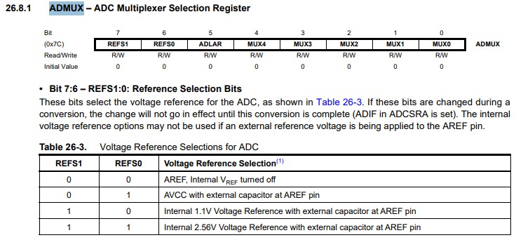
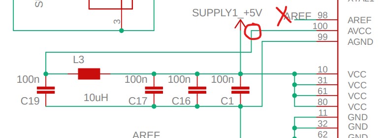
When
Mode REFS1:REFS0=0:1, AREF must not be connected to a voltage and AVCC
voltage will be used as the reference. Ideally, connect a capacitor at
AREF will be helpful but the current Skyboard doesn't have a cap on it,
which is fine.
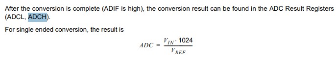
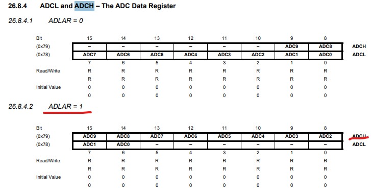
When
an ADC conversion is complete, the result is found in these two
registers. When ADCL is read, the ADC Data Register is not updated
until ADCH is read. Consequently, if the result is left adjusted and no
more than 8-bit precision is required, it is sufficient to read ADCH.
Otherwise, ADCL must be read first, then ADCH. The ADLAR bit and the
MUXn bits in ADMUX affect the way the result is read from the
registers. If ADLAR is set (ADLAR=1), the result is left adjusted. If
ADLAR is cleared (ADLAR=0 which is the default value), the result is
right adjusted.
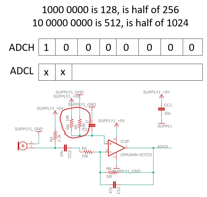
When
there is no input, the voltage divider provides a 2.5 V bias to the Op
Amp and the output should be 50% of the entire supply's voltage, which
is 2.5 V or 128 out of 256. You can just read ADCH and don't do anything to ADCL if you only need an 8-bit precision. If
you need higher precision, you need to read ADCL first then read ADCH.
However, the question is if you only read ADCH without shifting it
right by 2 bits, isn't it amplifying the result by 4 times? The answer
is no, when you only read ADCH, it recognizes that you are using an
8-bit precision so a 1000 0000 will be 128 or half of 256 or 2.5 V. If
you are using a 10-bit precision, a 10 0000 0000 is 512 or half of
1024, which is also 2.5 V but better precision.
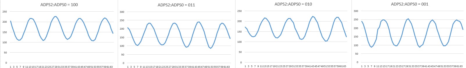
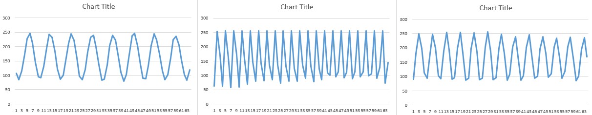
Human whistling is between 2 - 4 kHz A 25 us ISR for the ADC is giving you a 40 kHz sampling rate which should be sufficient.
16M/(40kx13)
= 30.78. The prescaler should be 30 or less. The follow examples show
you the results from prescalers to be 16, 8, 4, and 2 respectfully.
However, smaller prescalers will give you less accurate results, described as follows:
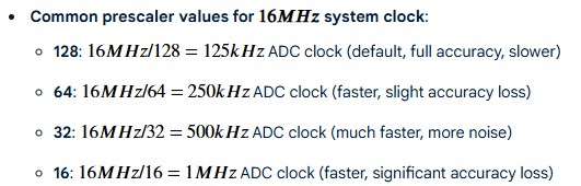
For
the same whistling, if you choose anything equal to or slower than 500
kHz (prescaler equal to or larger than 32), you are getting results as
follows (with the same whistling):
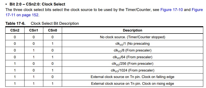
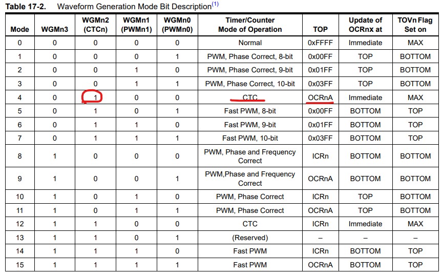
// Set to CTC mode (WGM12), no prescaler (CS10) TCCR1B |= (1 << WGM12) | (1 << CS10);
This time we are using TIMER1's CTC mode, which counts to the value stored in OCR1A then interrupts.
// Set OCR1A for 25µs (16MHz * 25µs - 1 = 400 - 1 = 399) OCR1A = 399;
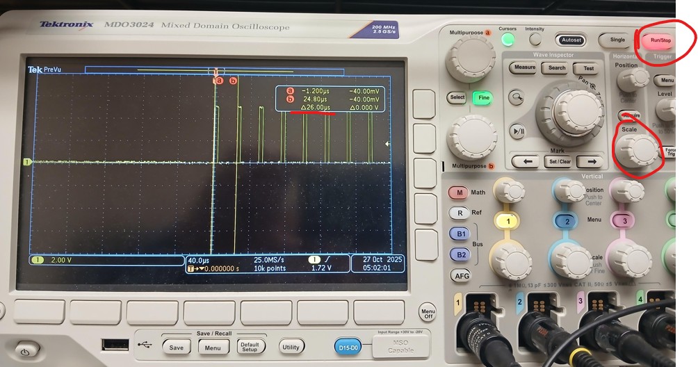
Use
a test pin to measure the ADC's sampling rate. My oscilloscope shows 26
us whcih is very close to 25 us. I pressed the Run/Stop button on the
scope to capture the pulses. This could be a little tricky since it
happens very fast. I used the Scale knob to zoom in to the pulses to
measure the distance between two rising edges.
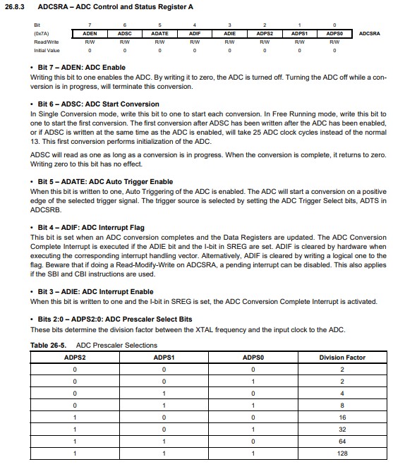
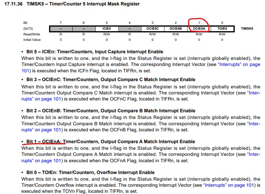
void setup() { pinMode(TEST_PIN, OUTPUT); Serial.begin(9600); // Configure ADC: A0, AVCC reference, left-justified result ADMUX = (1 << REFS0)| (1<<ADLAR); // Configure ADC: Enable, Prescaler=16M/(sampling rate x 13), 10-bit conversion takes about 13 cycles // Prescaler 10 or less should be fine ADCSRA = (1 << ADEN) | (1 << ADPS2); // Enable ADC Interrupt ADCSRA |= (1 << ADIE); // Configure Timer1 for CTC mode and interrupt cli(); // Disable interrupts TCCR1A = 0; TCCR1B = 0; // Set to CTC mode (WGM12), no prescaler (CS10) TCCR1B |= (1 << WGM12) | (1 << CS10); // Set OCR1A for 25µs (16MHz * 25µs - 1 = 400 - 1 = 399) OCR1A = 399; // Enable Timer1 compare interrupt A TIMSK1 |= (1 << OCIE1A); sei(); // Re-enable interrupts }
// Timer1 Compare Match A Interrupt Service Routine ISR(TIMER1_COMPA_vect) { digitalWrite(TEST_PIN, HIGH); // Start the ADC conversion ADCSRA |= (1 << ADSC); digitalWrite(TEST_PIN, LOW); }
// ADC Conversion Complete Interrupt Service Routine ISR(ADC_vect) { // Read the 8-bit result (we only need the high byte) // Read ADCL then ADCH to ensure consistency uint8_t low_byte = ADCL; // The Arduino ADC requires ADCL to be read first uint8_t high_byte = ADCH; if (sample_index < NUM_SAMPLES) { adc_reading[sample_index] = high_byte; // Use high byte for 8-bit result sample_index++; } else { // We have collected all samples, so stop the timer and set flag TCCR1B &= 0; // Stop timer sampling_complete = true; sample_index = 0; } }
Task 1 grading rubric: 1. TIMER 1 CTC mode ISR handles ADC conversion. (20 points) 2. Oscilloscope sampling rate verification - around 25 us. (20 points) 3. 64 whistling samples ploted - close to a sine wave. (20 points)
Task 2: Frequency Measurement
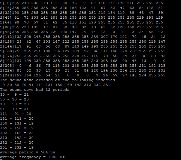
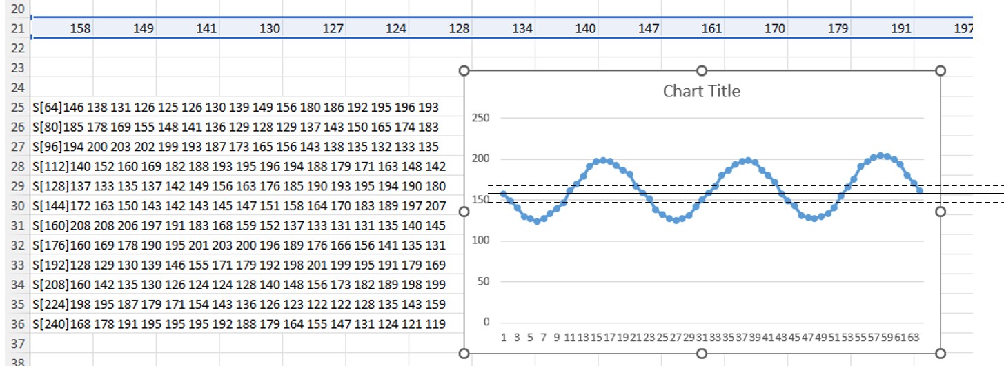
Log
256 samples when the user presses 'f' to fill the buffer. You must
whistle very close the microphone, and whistle it as loud as you can.
The successful pattern looks as follows, although these are just
numbers but you can still see an oscillating/periodic pattern in it.
You should have 8 - 12 periods for these 256 points and the frequency
of human whistle is 2 - 4 kHz, but I constantly whistled at a lower
pitch but it was still close to 2 kHz.
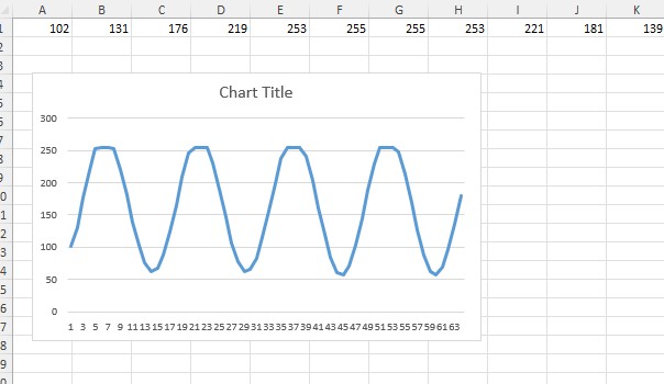
I
copied and pasted the whole data block from Putty and pasted them into
a spreadsheet. You can use the Data - Text to Columns option to split
them into different columns and plot them. In the following figure, I
manually did it for the first fours lines and plotted them. It showed
about 3 periods so you can predict that for the entire 16 rows, it'll
be around 12 periods for the 256 points. If you did it right, you
should have about 10 - 12 periods.
The
dashed line in the ploted figure shows the uppper threshold and lower
threshold, which were defined in the code. Again, the bias/DC offset
should be at 128 or 50% of the range, but it was at around 160 for me
so I just used 160 +- an error for the upperthreshold and
lowerthreshold valudes.
The setup() function is the same as the one for Task 1.
To
print 16 data points per line, when the index of the sample being ANDed
with 0x0F is 0, it means that there were just 16 points printed so you
can start a new line, print a line tag there, such as s[0], s[16], ...
..., s[240].
for (i = 0; i < NUM_SAMPLES; i++) { // print-out samples
if ((i & 0x0F) ==
0){
sprintf(buff,"\r\nS[%2d]", i);
Serial.print(buff);
}
sprintf(buff, "%3d ", adc_reading[i]);
Serial.print(buff); }
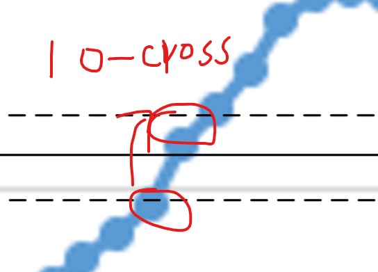
In
your loop() function, when the current data is lower than 160 and the
next is higher than 160 that means there is one zero cross event. This
current index should be logged into array cross[i]
As long as your signal crosses 0 (160) here for at least twice, we'll have at least one period of the signal logged.
if (crossCount>=2){
for (i = 0; i < crossCount - 1; i++) {
// Your Code //;
}
// Calculate the period and frequency based on the average period
period = // Your code//; // every two points is 25 us, times how many
points is the total time in a period
frequency = // Your code //;
;
sprintf(buff, "average period = %u us", period);
Serial.println(buff);
sprintf(buff, "average frequency = %d Hz", frequency);
Serial.println(buff); }
We'll need one ISR to start the conversion and another ISR (ADC conversion complete ISR) to log the data
// Timer1 Compare Match A Interrupt Service Routine ISR(TIMER1_COMPA_vect) { digitalWrite(TEST_PIN, HIGH); // Start the ADC conversion // Your Code //; digitalWrite(TEST_PIN, LOW); }
// ADC Conversion Complete Interrupt Service Routine ISR(ADC_vect) { // uint8_t low_byte = ADCL; // The Arduino ADC requires ADCL to be read first if you need a 10-bit precision uint8_t high_byte = ADCH; static myADCstates_t myADCstate = MIC_IDLE; static uint16_t index = 0; switch (myADCstate) { // and do what it tells you to do case MIC_IDLE: if (fillBuffer == true) { // Your Code //; } break;
case
MIC_WAIT_FOR_TRIGGER: