STM32
Microcontrollers Basics
1. Introduciton. (copied from here)
The STM32 series are some of
the most popular microcontrollers used in a wide variety of products.
They also have an excellent support base from multiple microcontroller
development forums. The STM32 family of microcontrollers from
STMicroelectronics is based on the ARM Cortex-M 32-bit processor core.
STM32 microcontrollers offer a large number of serial and parallel
communication peripherals which can be interfaced with all kinds of
electronic components including sensors, displays, cameras, motors,
etc. All STM32 variants come with internal Flash memory and RAM.
The range of performance available with the STM32 is quite expansive.
Some of the most basic variants include the STM32F0 and STM32F1
sub-series that start with a clock frequency of only 24 MHz, and are
available in packages with as few as 16 pins. At the other performance
extreme, the STM32H7 operates at up to 400 MHz, and is available in
packages with as many as 240 pins. The more advanced models are
available with Floating Point Units (FPU) for applications with serious
numerical processing requirements. These more advanced models blur the
line between a microcontroller and a microprocessor. Finally, the
STM32L sub-series is designed specifically for low-power portable
applications running from a small battery.
Development Tools Development tools are required to develop the code,
program the microcontroller and test/debug the code. The development
tools include:
- Compiler
- Debugger
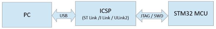
- In-Circuit Serial Programmer (ICSP)
There are several software development tools available for code
development on STM32 microcontrollers. The software tools are available
as Integrated Development Environments (IDE) which combines all of the
necessary tools into an integrated environment.
Apart from the software tools, an In-Circuit Serial Programmer
(ICSP) is required to program and test the code on the actual
microcontroller. The ICSP is required to interface the microcontroller
to the PC software tools via a USB port.
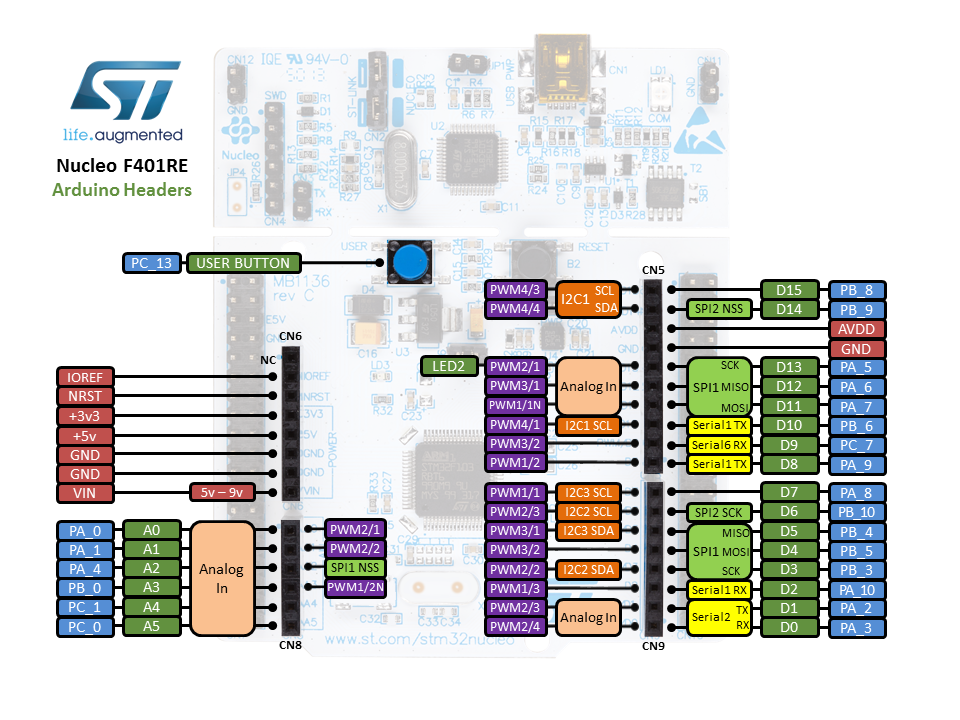
The development board we are going to use in these tutorial series is the NUCLEO-F401RE board.
2. The C language used in CubeIDE.
There is an online textbook written by Dr. Jonanthan W. Valvano and
Ramesh Yerraballi, who are professors at UT Austin. The free online
book is available on UT's website.
http://users.ece.utexas.edu/~valvano/embed/
It is critical to understand the C programming language before you move forward with any professional MCU programming projects.
Read Chpaters 2 - 10 as quicky as possible to understand the basics of C programming for Embedded Devices.
3. Get started
If you use your own PC, go to https://www.st.com/en/development-tools/stm32cubeide.html#get-software
to download the STM32 Cube IDE for your operating system. It may
require registration and email verification before you can download it.
Install it.
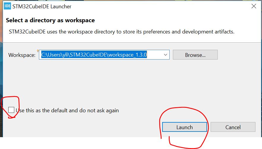
Double click to open the IDE.
The user will be asked to set up the
Workspace directory at the first time. It is ok to use the default one.
Create a new project:
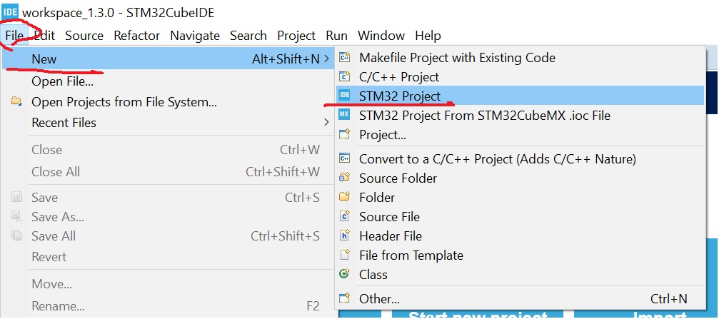
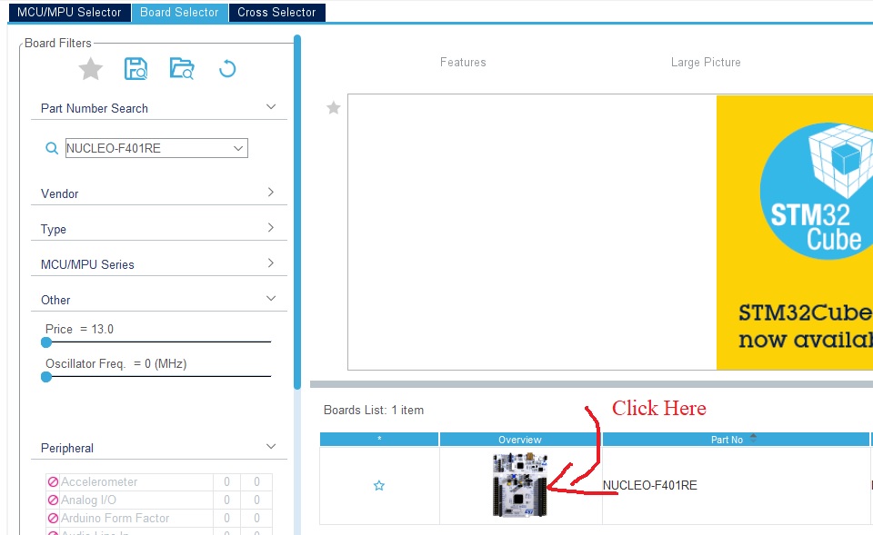
Select the correct board:
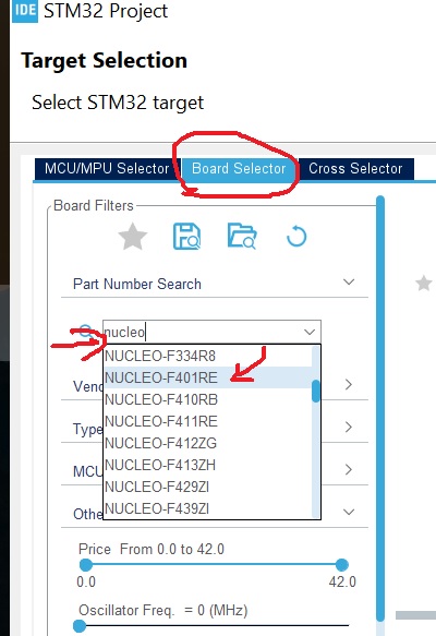
Pick up the board and click
"Next'.
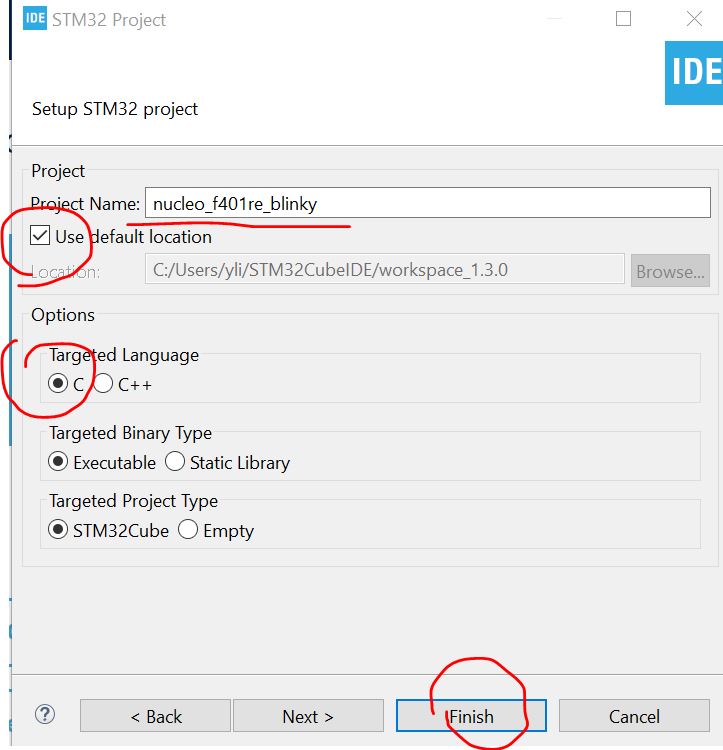
Name your project.
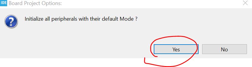
If it is not a bare-bone MCU,
click YES. (for here, apparetnly we are using a demo board so click
YES).
This takes time at the first
time you initialize it. Be patient.
Find the datasheet for the
STM32 F401 family Hardware Abstraction Layer (HAL) by googling
'stm32f401 hal'.
The pdf can be downloaded from my server
as well.
On Page 406 of the tutorial,
you can find the HAL_GPIO_TogglePin function:

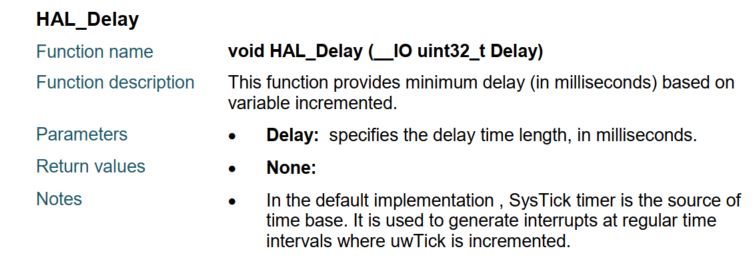
On Page 83, you will seet the
time delay driver/library:
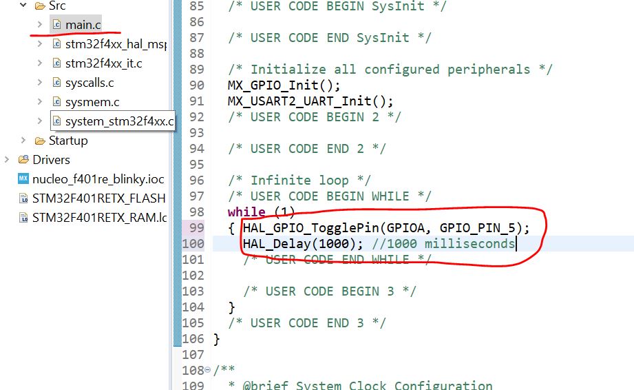
From the .ioc file, you can
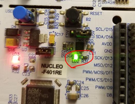
see that PORT A number 5 is connected to a greeen LED on the board.
Let's try to blink it.
Double click the 'main.c'
file, type the following code into the 'while (1)' function block. Keep
in mide that the code should be within the /* USER CODE BEGIN WHILE
*/ /* USER CODE END WHILE
*/ block.
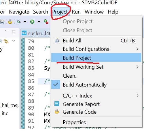
Build the project.
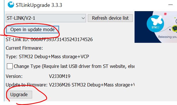
Run it. If you are asked to
update the firmware, go ahead and do it.
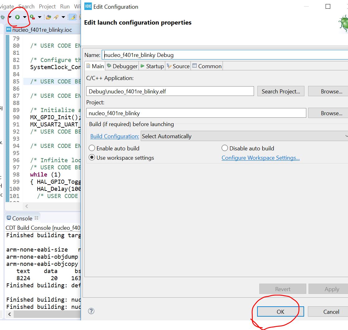
After this, you should be
able to see the green LED blinks on the board.
A side note: The debug
function is very handy when the project is massive. Find out how to set
up a breaking point for debugging when you run the code on the chip in
real-time in this video:
https://www.youtube.com/watch?v=hyZS2p1tW-g&t=332s
4. UART examples
4.1 Send a string to the serial monitor
Follow the same procedure to create a new project called 'UART_dataTypes'.
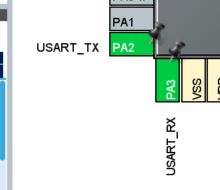
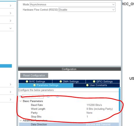
In Pinout tab that USART2 mode in configured to Asynchronous, PA2 is connected to USART2_TX and PA3 is connected to USART2_RX.
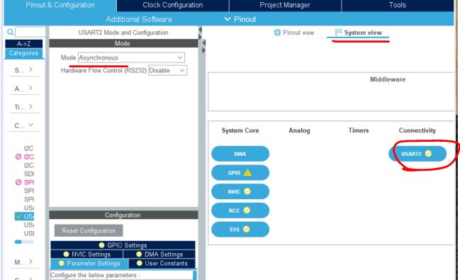
Make sure the settings are as follows.
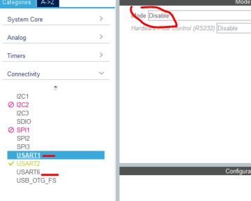
Make sure other USARTs are disabled.
Go to Project - Generate Code
Copy the following code to the specific location and click run.
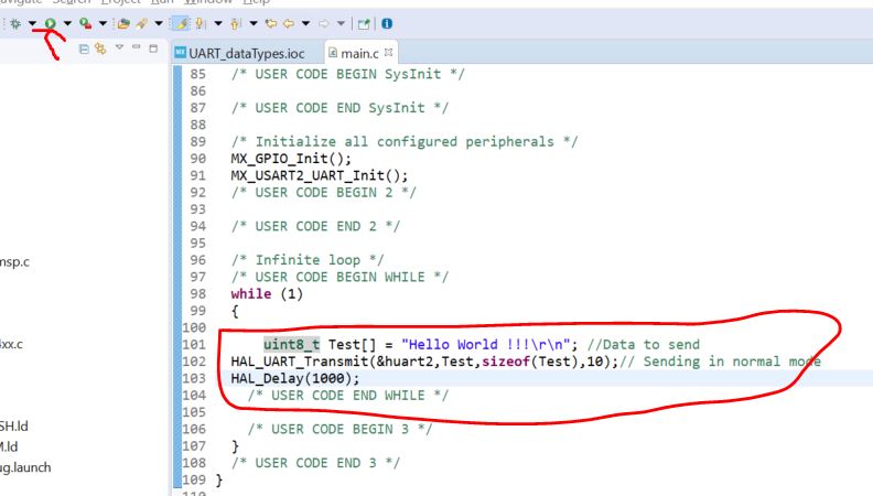
(The full script can be found here but I don't think you need to copy the auto-generated lines)
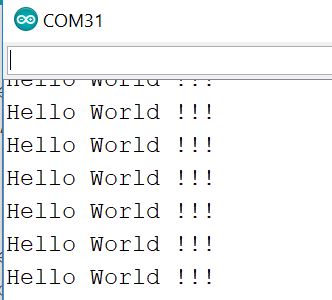
Open an Arduino IDE's
serial monitor or any other monitor you may have on your computer. Make
sure the COM port number is correct. Use Device Manager to check the
COM port number if you use a Windows PC.
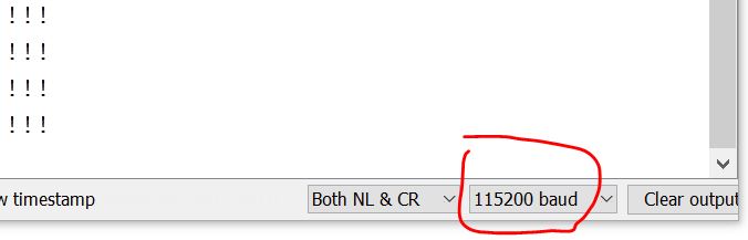
You should see this in the serial monitor. (Make sure the data rate in
the serial monitor mathces the settings in your STM32 MCU.
4.2 Echo any data received over UART
The purpose of this
experiment is to send anyting to the STm32 MCU through USART and the
MCU will echo the received data and send it back to the USART serial
monitor.
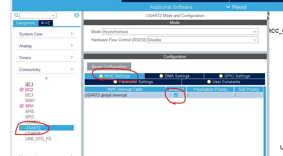
Before you proceed, enable the interrupt for USART2. Don't forget to save it (ctrl c) and generate the code.
Come back to the
main.c script, delete the added code in the last section. Add these
code to the specific locations in the script. The full code can be
found here.
/* Private variables ---------------------------------------------------------*/
UART_HandleTypeDef huart2;
uint8_t byte;
/* USER CODE BEGIN PV */
/* USER CODE END PV */
/* USER CODE BEGIN 0 */
//Add a callback function to handle the receive interrupt and transmit the received byte.
/* This callback is called by the HAL_UART_IRQHandler when the given number of bytes are received */
void HAL_UART_RxCpltCallback(UART_HandleTypeDef *huart)
{
if (huart->Instance == USART2)
{
/* Transmit one byte with 100 ms timeout */
HAL_UART_Transmit(&huart2, &byte, 1, 100);
/* Receive one byte in interrupt mode */
HAL_UART_Receive_IT(&huart2, &byte, 1);
}
}
/* USER CODE END 0 */
/* USER CODE BEGIN 2 */
//enable the driver to receive 1 byte. This function enables the RXNE interrupt bit.
HAL_UART_Receive_IT(&huart2, &byte, 1);
/* USER CODE END 2 */
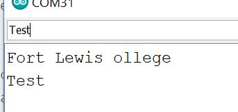
After the code is ready, directly run the code. Open an Arduino IDE
serial monitor, type anythingin the serial monitor, it should be able
to receive the same thing you sent to the MCU.
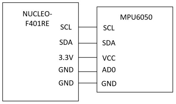
5. I2C communitation with the accelerometer/gyroscope MPU6050
Repeat the process in the last section to creaete a new project called 'nucleo_f401re_mpu6050'
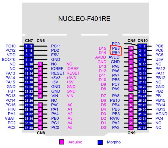
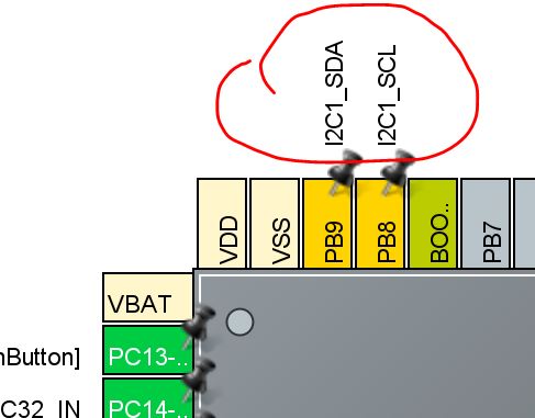
From the pinout of the Nucleo-F401RE board, we know that PB8 is the SDL pin for I2C, and PB9 is the SDA pin for the I2C.
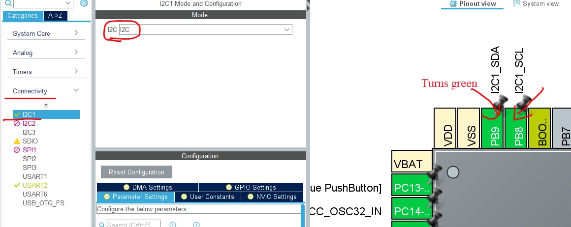
Set PB8 and PB9 as the I2C1_SCL and I2C1_SDA respectively. (single left click)
On the left side, enable I2C in the drop down menu: Once the PB8 and
PB9 pin tags on the right side turns green, the setup is done.
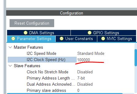
The default I2C data transmission rate is 100 kHz which is good for
most of the I2C devices. You don't have to change any of the default
settings here for now.
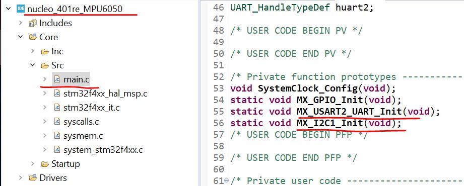
Then do File - Save, and Project - Generate Code.
In the main.c file, you will see that the I2C and the USART ports have been initilized.
All the other necessary script for I2C initialization and communication can be found here.
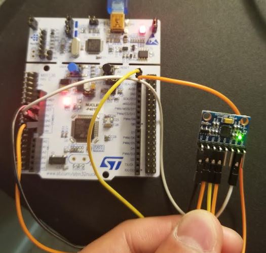
Make the following hardware connection.
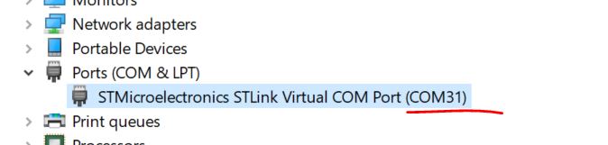
In Windows, use Device Manager to find the port being used. COM31 in my case:
We need to set up the UART because the data collected through I2C will
be sent to a Serial Monitor on your PC to visulize the data so you know
it works.
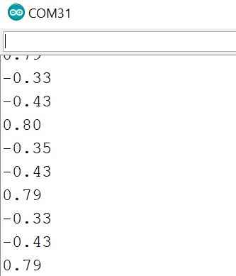
Start an Arduino Serial Monitor to check the results. You can also use any other serial monitors you have on your computer.
Keep in mind that there is nothing to do with your Arduino board. This is just a serial monitor APP in your Arduino IDE.
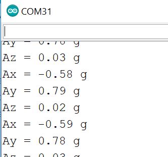
This is what you will see in your serial monitor.
You may see warnings regarding the second argument of
'HAL_UART_Transmit' has a different signedness. The reason is 'char' is
signed, the pointer in 'HAL_UART_Transmit' is unsigned. You need to use
a pointer for the data argument in 'HAL_UART_Transmit' instead of the
data itself.
The updated solution can be found here. I also added the 'Ax =', 'Ay =', 'Az =', and the unit - 'g'.
You should see this:
Tasks
Complete all the experiments in this tutorial (50 points)