Lecture
37 Get Started with Raspberry PI and PyQt
1. Introduction to the Raspberry PI (RPI)
Raspberry
Pi is a small single board computer. By connecting peripherals like
Keyboard, mouse, display to the Raspberry Pi, it will act as a mini
personal computer. Raspberry Pi is popularly used for real time
Image/Video Processing, IoT based applications and Robotics
applications.
Raspberry Pi is slower than laptop or desktop
but is still a computer which can provide all the expected features or
abilities, at a low power consumption. Raspberry Pi Foundation
officially provides Debian based Raspbian OS. Also, they provide NOOBS
OS for Raspberry Pi. We can install several Third-Party versions of OS
like Ubuntu, Archlinux, RISC OS, Windows 10 IOT Core, etc. Raspbian OS
is official Operating System available for free to use. This OS is
efficiently optimized to use with Raspberry Pi. Raspbian have GUI which
includes tools for Browsing, Python programming, office, games, etc. We
should use SD card (minimum 8 GB recommended) to store the OS
(operating System).
Raspberry Pi is more than computer as it
provides access to the on-chip hardware i.e. GPIOs for developing an
application. By accessing GPIO, we can connect devices like LED,
motors, sensors, etc and can control them too. It has ARM based
Broadcom Processor SoC along with on-chip GPU (Graphics Processing
Unit). The CPU speed of Raspberry Pi varies from 700 MHz to 1.2 GHz.
Also, it has on-board SDRAM that ranges from 256 MB to 1 GB. Raspberry
Pi also provides on-chip SPI, I2C, I2S and UART modules. There are
different versions of raspberry pi available as listed below:
Raspberry Pi 1 Model A
Raspberry Pi 1 Model A+
Raspberry Pi 1 Model B
Raspberry Pi 1 Model B+
Raspberry Pi 2 Model B
Raspberry Pi 3 Model B
Raspberry
Pi Zero
Caution:
Please
try to not touch the metal pins/compoments on the board. Try to hold
the edges. The static
shock from your finger can kill the IC chips on the board:

2. The First Experiment with the PI board
2.1 Set up your RPI board
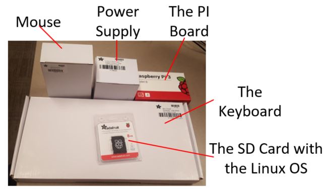
The
following figure shows the parts needed for the experiment:
A RPI board
A mouse
A power supply
a keyboard
a SD card (has the Debian Linux OS in there)
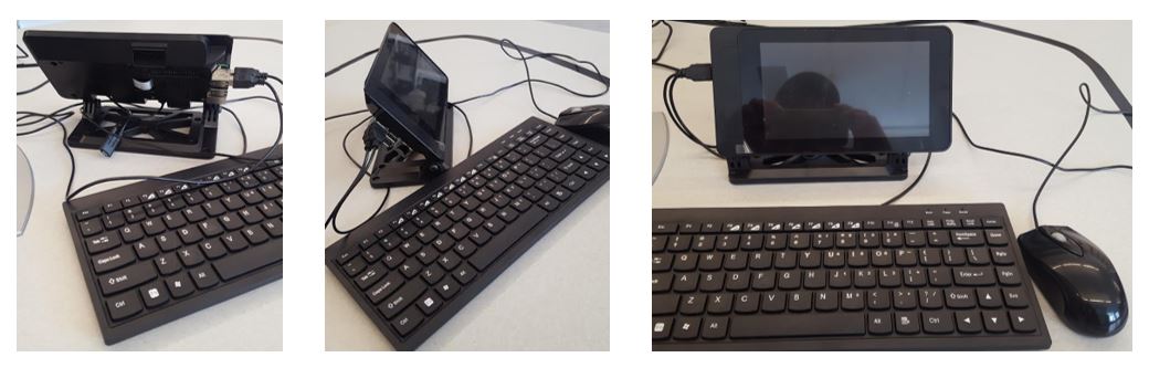
I found a very nice case for the RPI board to make this little board
looks more like a real computer.
Before you put your RPI board into the case, make sure you have the SD
card inserterd into the board

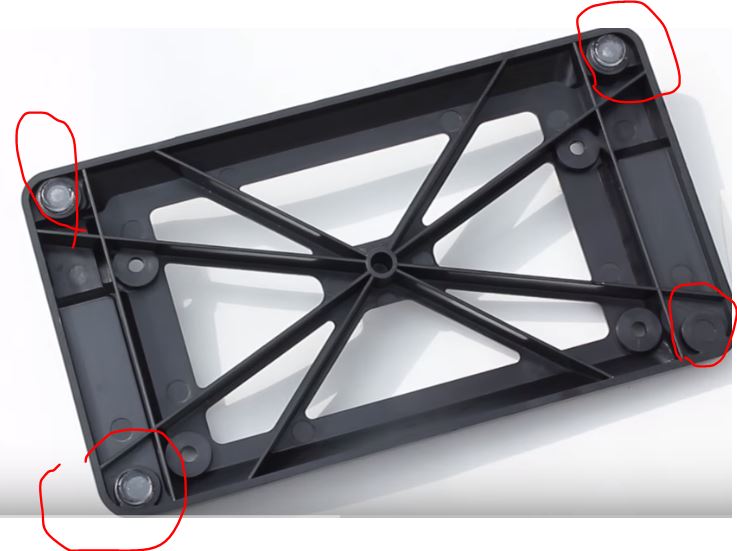
First, install the four rubber corner protectors at the four corners of
the plastic support of the touchpad:
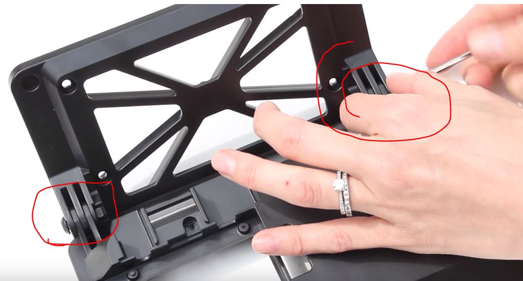
Then connect the case to the support at the joint use the
given bolts and nuts:
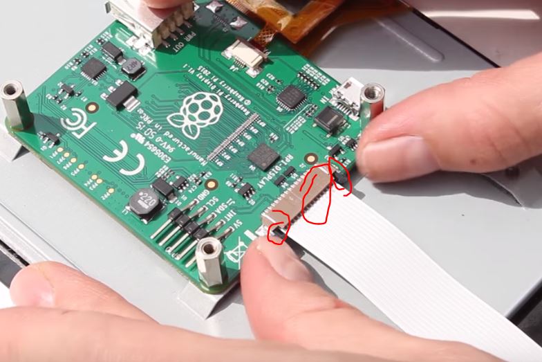
Plug in the Flexible Flat Cable (FFC) to the touch pad control board
(not to the RPI board yet!!!!):
In the following figure, the 'metal' side of the FFC is facing UP.
Gentally bend the FFC and mount your touch pad to the box:
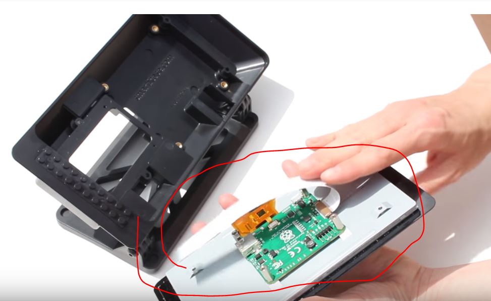
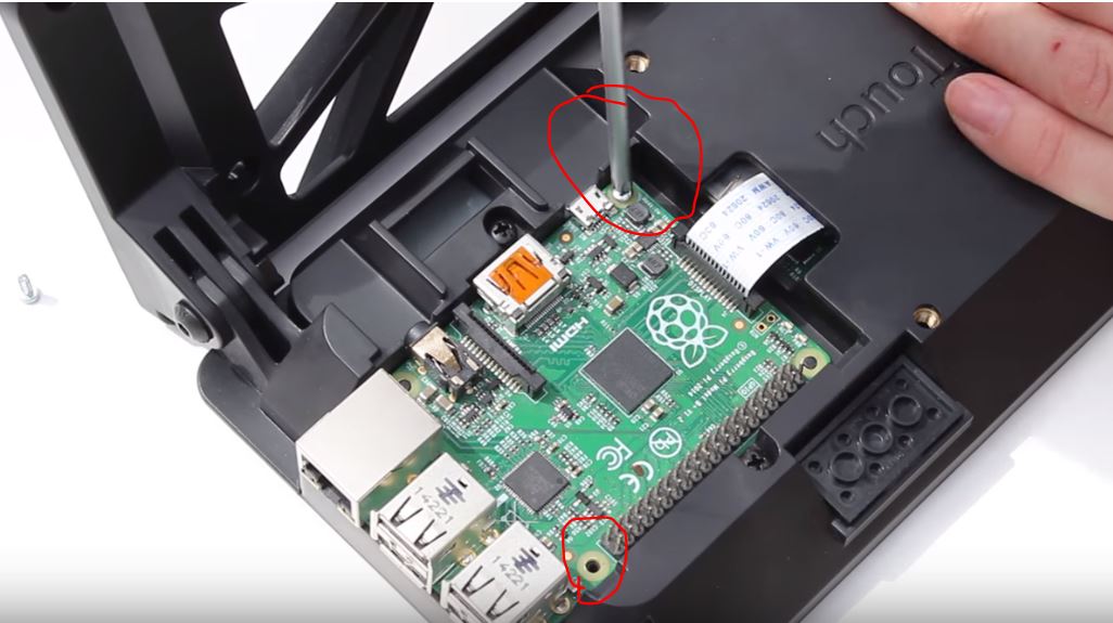
Screw in the bolts to mount the PRI to the cover:
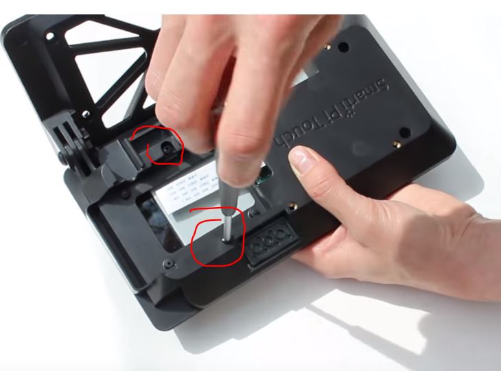
Gentally put the board into the slot:
Mount it to the holder use the stainless steel screws:
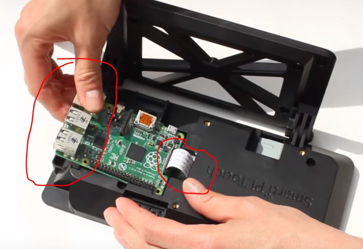
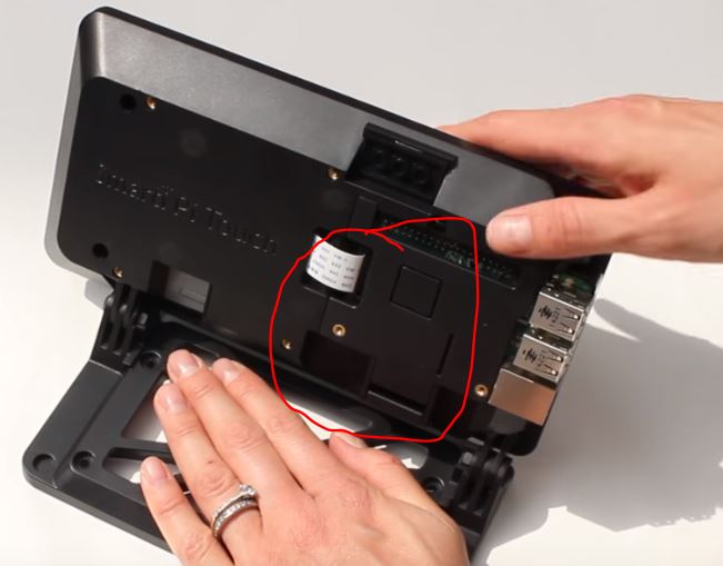
Put the board cover at the back to the case:
Connect the microUSB adapter to the USB port of the PRI board and the
touch pad control board:
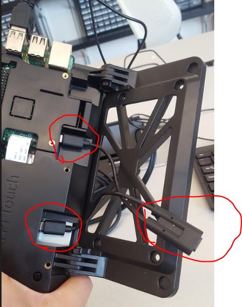
The other end of the adapter should be connected to the power supply.
Then plug in the mouse and keyboard to the RPI board, your mini RPI
computer is ready to roll!!
You can also follow the video at the link below to assmeble the case
and the RPI:
https://www.youtube.com/watch?v=XKVd5638T_8
2.2 Print a label of your name and put it at the back of the case:
For the rest of the lectures, please always take your RPI board.

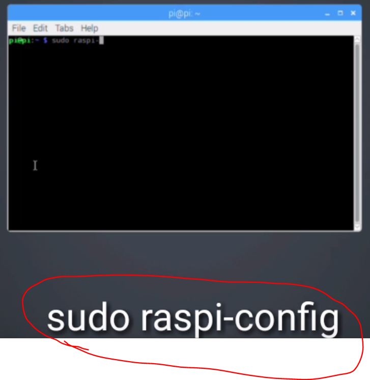
2.3 Fix the keyboard incorrect character issue (@, #, & .....)
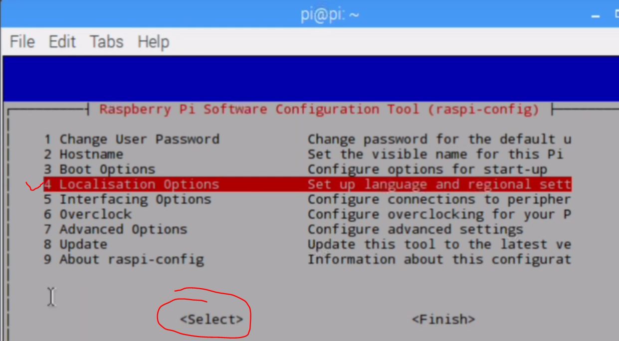
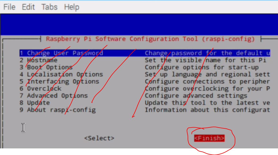
Turn on the command line terminal and type 'sudo raspi-config':
Then move the arrows on the keyboard to select 'Localisation Options':
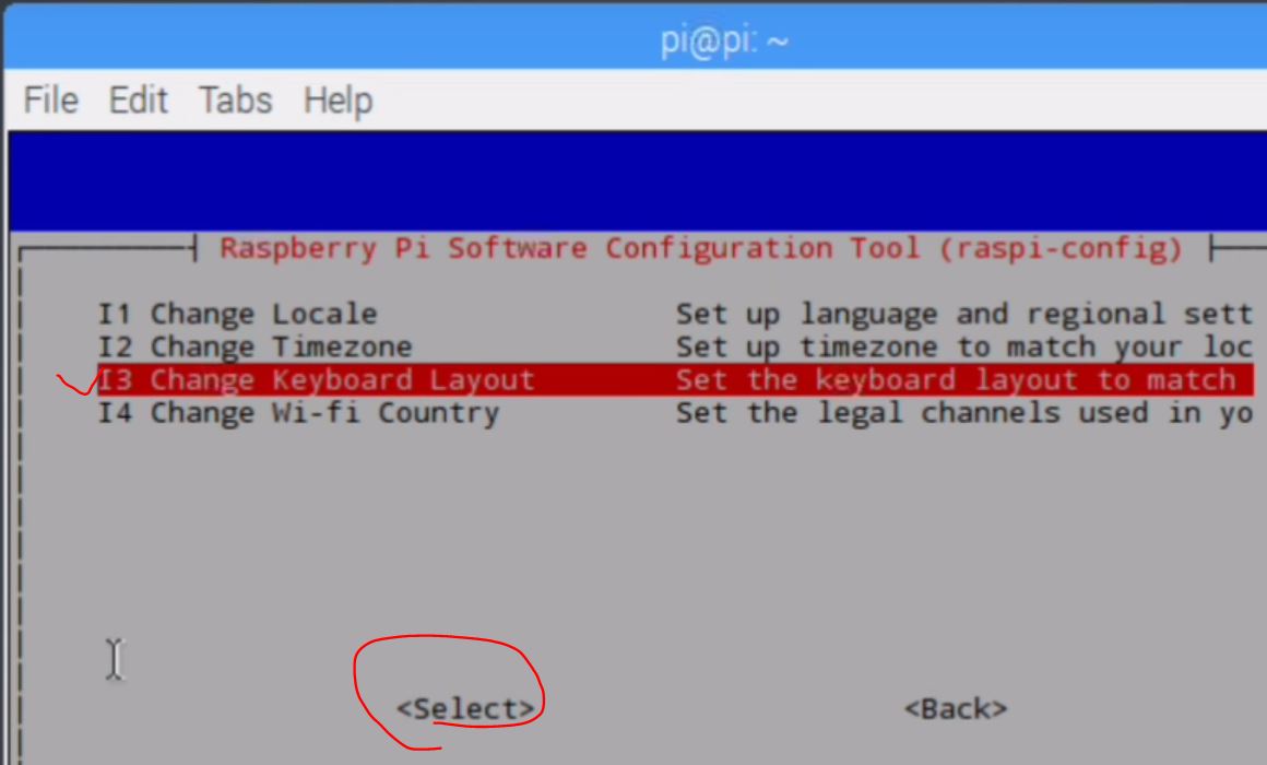
Then select 'Change Keyboard Layout':
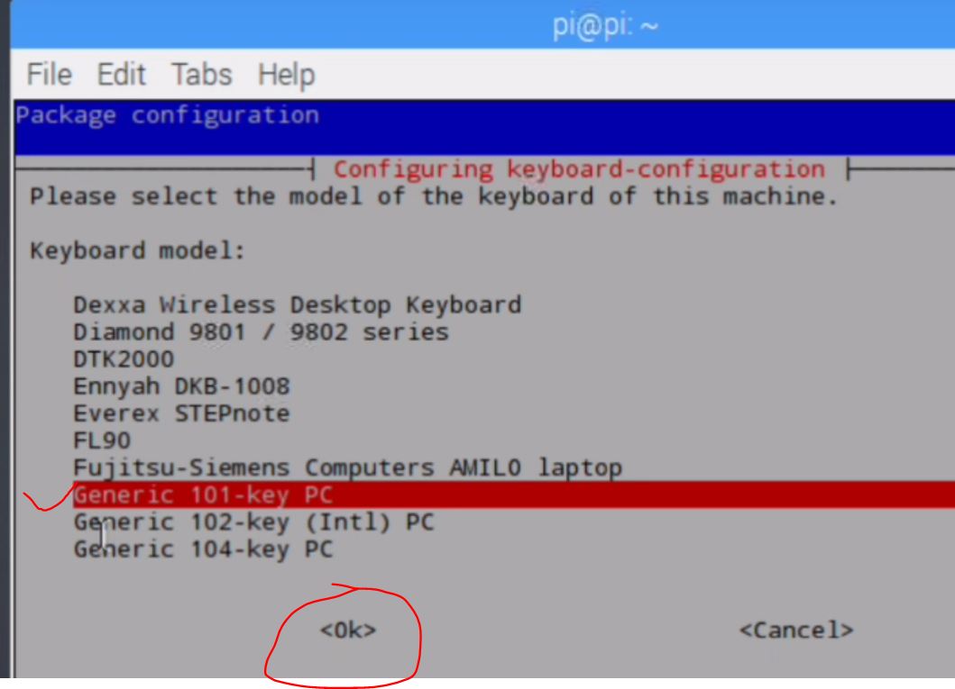
Then select 'Generic 101-key PC':
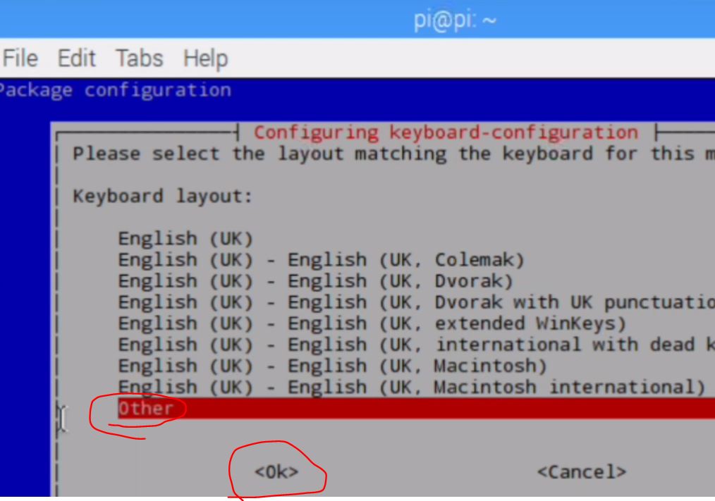
Then 'other':
Then:
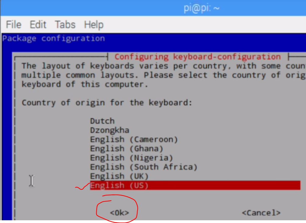
Then:
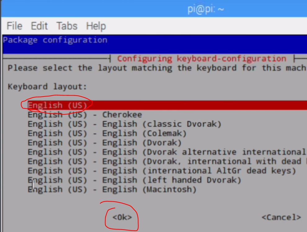
Then:
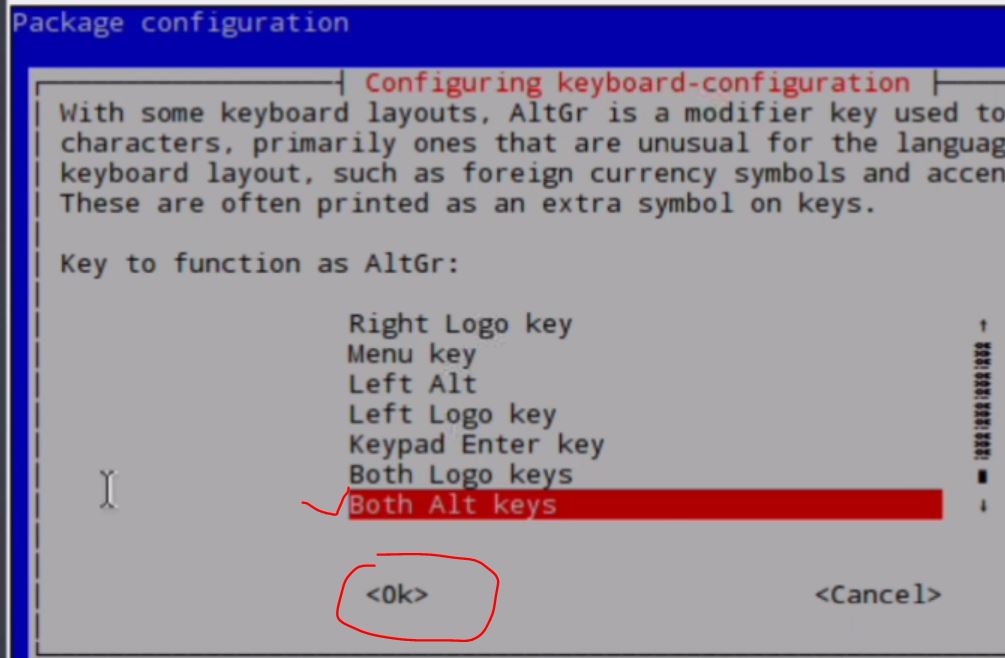
Then:
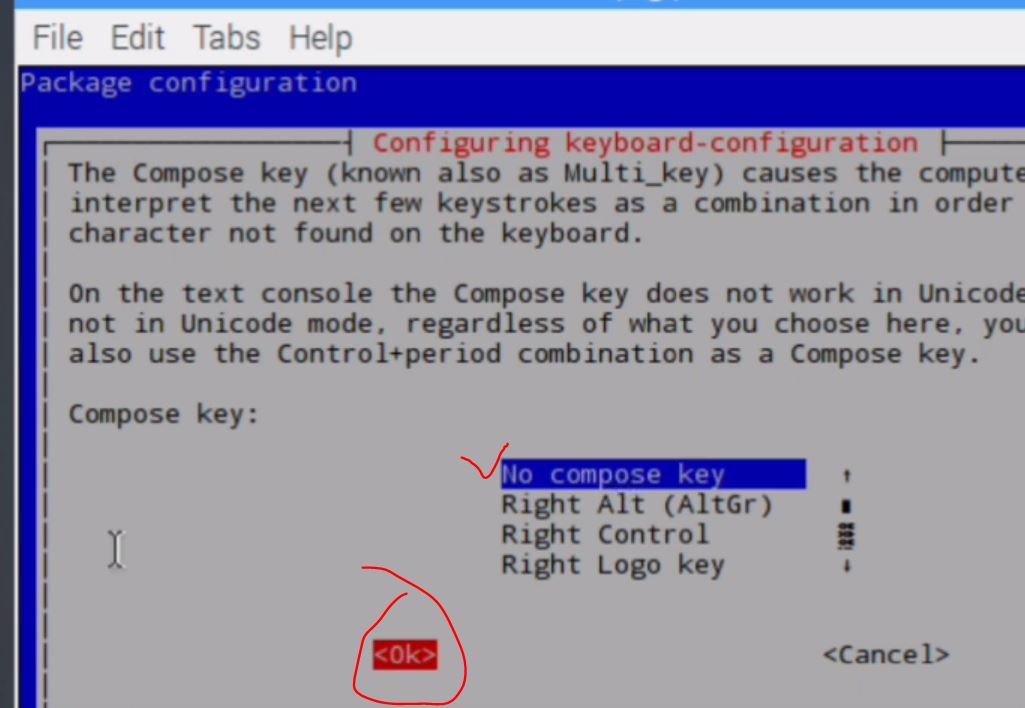
Then:
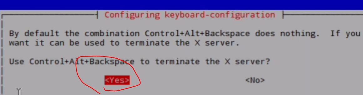
Then come back to the starting window, select 'Finish'.
You can also find the instruction for changing the keyboard issue at
the link below:
https://www.youtube.com/watch?v=t02Rc8NPt5w
2.4 Update your RPI (important)
Connect
the RPI board to the FLC-Guest WiFi network, in the command line
window, update the linux packages use: 'sudo apt-get update'
In
the command line window, Type: 'python --version' + Enter, should
return you the current python version installed. It might be Python
2.7, however, we have beening learning Python 3. We need to set the
'python alias' to be 'python 3.4' but not 'python 2.7'. Do as follows
in the command line:
alias python='/usr/bin/python3.4'
After this setup, when you type 'python --version' in the command line
window, you should see 'python 3.4' to be returned.
To
open a '.py' file in 'vim' in the RPI linux system, you should use 'vi
test.py' to open it. When you want to run the code in 'vi', you should
do '! python3.4 %' instead of '! python %' as you did in the Windows
OS.
3.
Turn on an LED by running the program on the board:
1. Connect the USB cable of the keyboard and the mouse to the RPI
Board.
2. Make sure the SD card is in the socket on the board.
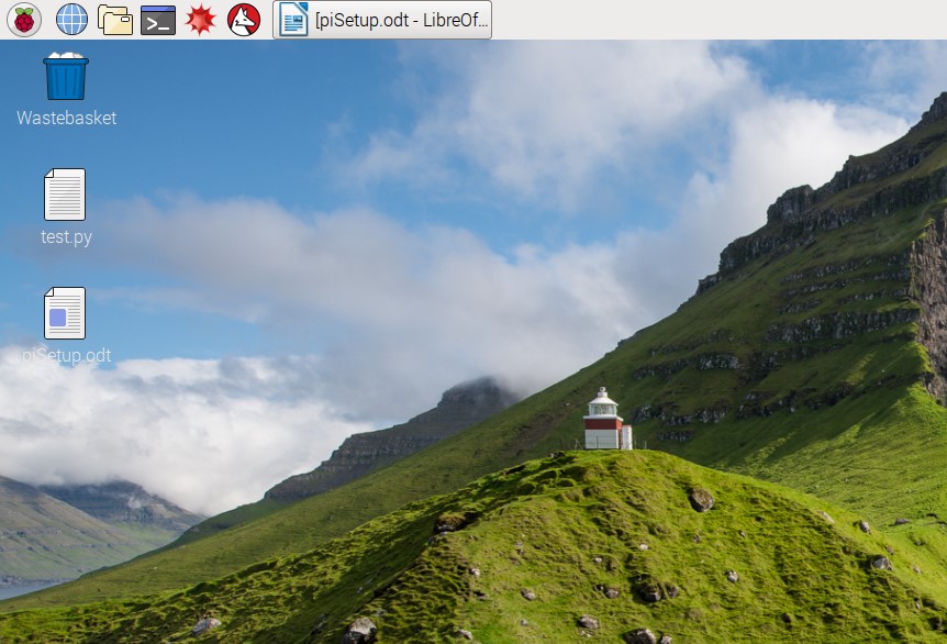
3. Power up the board and just wait for a bit. You should see the Linux
operating system desktop similar to this: (may have a different
backgroud):
If
you want to shut down the RPI board, please DO NOT directly plug-off
the power cable. Go to the start menu and shut it down over there!!!
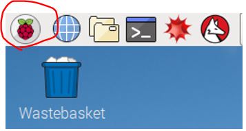
Click the Raspberry icon (the start menu) on the top-left
corner of the
view, select Programming - Python 3 (IDLE) to open the console.
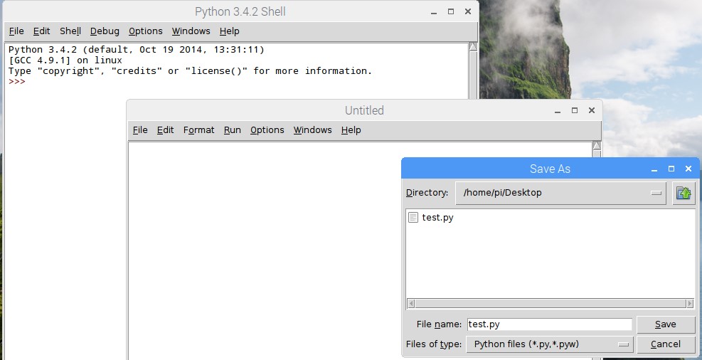
To
open an independent script file, select File - New File. In the new
window, select File - Save As. Ust test.py as the file name and save it
on the desktop of the linux system.
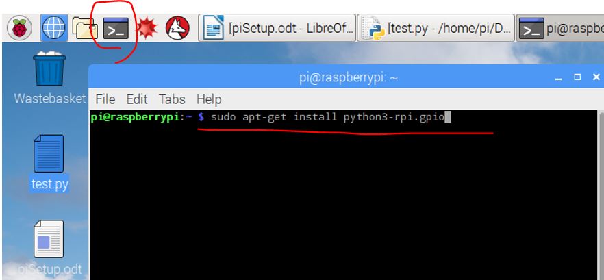
Open a linux
terminal, install rpi.gpio package: (make sure you have
the wifi connection):
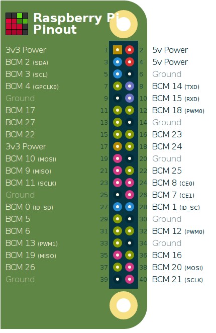
According to the
Pin Map of the PI board, connect BCM 23 to the
resistor, and connect any of the GROUND pin to the cathode of the LED.
The Pin Map can
be found below:
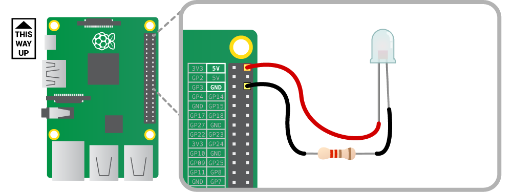
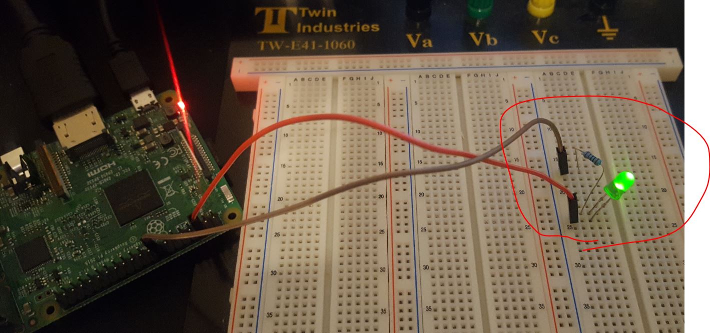
Before
you connecct the LED to a GPIO pin, connect it as the shown in the
following figure first to make sure your LED is working properly:
Please
keep in mind that, the LONGer pin of the LED is the Anode, should be
connected to the higher voltage end. The shorter pin of the LED should
be connected to the resistor and then to the GND (0V) pin. The resistor
can be 100 ohm - a few hundred ohms, it is just to project the LED
getting burned by the current.
If the LED works
fine, connecct the RED wire in the figure above to the BCM 23 pin on
the RPI board.
Type the
following code into your new script window and save it.
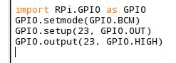
This will turn
on Pin 23 permanently. A dead loop is bad, the PI will
run this forever, which is power-consuming.
You can make the
LED flash for a certain period of time and turn it
off:
Modify the code:
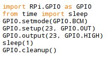
Then, run this
code at the Linux terminal:
>>
sudo python test.py
The LED will be
turned on for 1 second and then off. You can modify the
number in the 'sleep()' function to change the delay time. It can be
even 0.1s, or 0.01s, etc.
4. Toggle LED by a pushbutton on the GUI
We
are going to use the 'tkinter' Class to build a simple GUI to toggle
the LED connected to the RPI board. This is just the first time we run
a GUI in Linux/RPI. In the future, we will use the 'PyQt' Class to
build GUIs instead of using 'tkinter'.
Keep
in mind that, the 'tkinter' Class is great and powerful. Work on this
only may take you the entire semseter to learn and become a
professional. 'PyQt' can do the similar job as 'tkinter' but PyQt is
more popular and there are more job positions/postings asking for PyQt
skills but not tkinter skills.. We don't have time to explore both so
we'll pick up PyQt for our experiments.
Type
the following code into a new script file, test_1.py, click Run in the
menu.
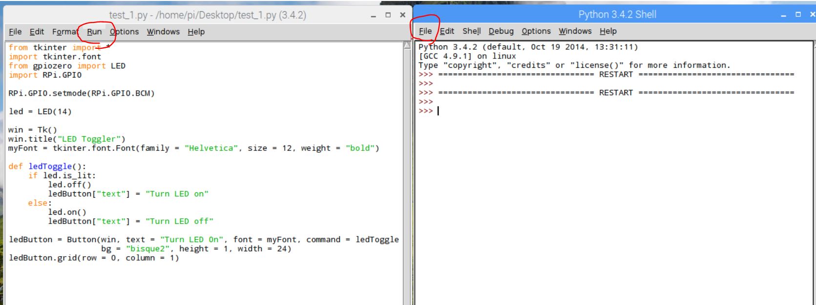
A
short demo video can be found below:
5. Push your code to
GitHub
and send me the link of the repository to the home work email. (You can
directly push it to GitHub in the RPI environment, Linux has git and
vi).
Tasks:
Follow
the
tutorial and repeat all the work I've done there. Demonstrate your work
to me in class. Raise your hand when you are done for each task so I
can check these boxes on my grade paper.
Section 1: 20 points
Section 2: 20 points
Section 3: 25 points
Section 4: 25 points
Section 5: 10 points
(There are no due dates for these demonstration tasks here and in the
future.
As long as you can get it done before the final exam, you'll be able to
get the credit for these. You just need to demonstrate it to me in
person).