CE 432 Robotics II Fall 2021
Sensors and Actuators Assignment
Sean Eaton
smeaton@fortlewis.edu
Sensors and Actuators Assignment
Introduction:
We were tasked with using a variety of different
sensors and actuators in this assignment. This involved understanding
the wheatstone bridge circuit used for strain gauges, using an
ultrasonic distance sensor without using a library, designing a pulse
detector, designing a vibration detector, controlling the NEMA17
stepper motor's speed and direction with a joystick, and finally using
a rotary encoder. All of these designs were done using an Arduino Uno
and a couple of the sensors used can be found in many Arduino kits.
Prior to this assignment I had some experience using the ultrasonic
sensor and the MPU6050 inertial measurement unit (IMU). In addition
this, I knew how to use the Open-Smart 2.4 GHz transceivers and the
NEMA17 stepper motor from the previous assignment.
Problem 1: Explain why the full-bridge Wheatstone Bridge is the most sensitive one to resistance variations.
The quarter-bridge Wheatstone bridge is the least sensitive to
resistance variations. This is because the changes in resistance tend
to be tiny and as shown in the calculations below, this tiny change in
resistance is also being divided by 4.
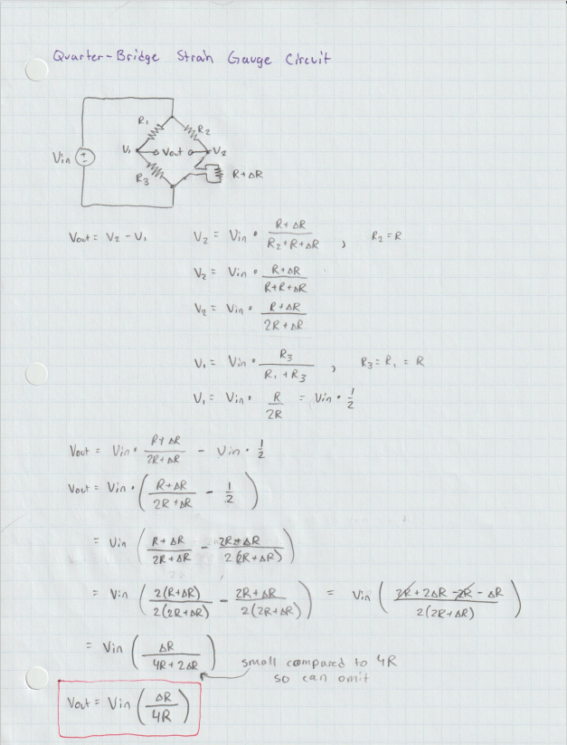
Figure 1. Calculating Vout for the quarter-bridge Wheatstone circuit.
Next, the half-bridge Wheatstone bridge has medium sensitivey to
resistance variations. It is more sensistive than the quarter-bridge
variation since the change in resistance is being divided by 2 now
rather than 4.
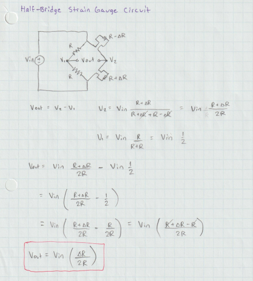
Figure 2. Calculating Vout for the half-bridge Wheatstone circuit.
Finally, the full-bridge Wheatstone bridge is the most sensitive to
resistance variations. This is due to the change in resistance being
divided by 1 now instead of 2 or 4.
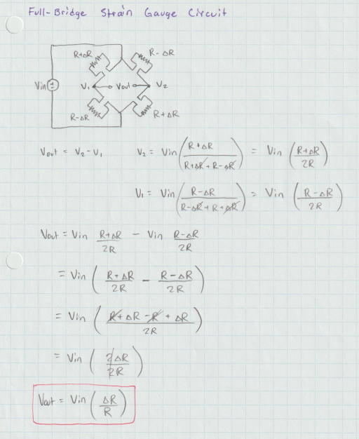
Figure 3. Calculating Vout for the full-bridge Wheatstone circuit.
From the calculations it is evident that the full-bridge Wheatstone
bridge is going to be the most sensitive to changes in resistance. If
measurements were taken in the exact same way, the quarter-bridge
output will only be 25% of the full-bridge output and similarily the
half-bridge output will be 50%
Problem 2: Create a sketch that can measure distance using the HC-SR04 ultrasonic module without using the SR04.h library.
The HC-SR04 measure's distance by outputting an ultrasonic pulse and
measuring the duration of the return pulse so that distance can be
calculated. Since this module works by outputting an ultrasonic sound
wave it can have issues detecting softer things like fabric.
The equation used for calculating distance was provided in one of the
slides used in lecture. I made one modification to it however. I
decided to multiply by 0.034 rather than 0.0343 because of the
datasheet and it seemed to give me slightly more accurate values than
the 0.0343 value.
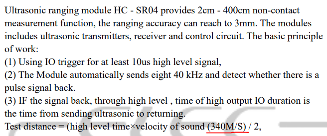
Figure 4. Screenshot of the HC-SR04 datasheet specifying the 340 M/S value.
A video of the HC-SR04 design can be seen below. I used a Coke can I
had available to demonstrate the distance sensing capabilities. I also
checked the distance using a measuring tape I had available and it is
pretty close. It seems to be above by about 0.5-0.7 centimeters
however, which is suitable for small projects like this but probably
isn't for applications that need to be more accurate.
Problem 3: Design a pulse detector using an UNO board. Design a
program to let your UNO board sense the pulse and deliver a 400 us
pulse 800 us later than the input.
For problem 3, the Arduino Uno had to be programmed so that a pulse
could be detected. I accomplished this by setting a pin as an input and
digital reading the pin to detect if there is a state change. If there
is a state change, I then checked if it was the rising edge or falling
edge of the pulse. If it was a rising edge I then delayed by 800 us,
set the output pin to HIGH, delayed for 400 us, and then set the output
to LOW again. If a falling edge was detected I made sure the output was
set to LOW so that the output is at its default state (no pulse
detected). Originally I decided to output the state to the Serial
monitor as well so I could verify functionality that way but I was
surprised to find that it added significant delay to my output pulse. I
needed to remove the Serial print statements to get the correct 800 us
delay and 400 us on time. A video of the results can be seen below. I
change the frequency to demonstrate that the output pulse always emits
800 us after the input pulse is detected.
Problem 4: Use a MPU6050, an Arduino UNO, and a buzzer to create a vibration detector (for the Z direction only).
The vibration detector was accomplished using the MPU6050 module to
detect changes in the gyroscope values in the Z direction. The MPU6050
is an inertial measurement unit and is able to return accelerometer and
gyroscope values. I used a library for the MPU6050 module that I found
via some research into simple libraries I could use. I ended up
deciding to use the MPU6050 library written by tockn, whose GitHub can
be found here.
By using the library, calibration was handed for me which was nice. All
I had to do was keep the MPU6050 module still during the setup loop.
After this I also ran a for loop to detect the maximum and minimum
values for the gyroscope on the Z axis. The for loop I used collects
5000 values while the MPU6050 is still so that I can use the max and
min to detect a noticable change in the MPU6050's orientation in the Z
direction. Once a measured value is above or below the MPU6050's rest
values I then made the buzzer to emit a 450 Hz sound for 1 second
before being turned off. The 450 Hz sound is arbitrary and based on a
tutorial I found for using a buzzer. A video demonstrating the
functionality of the vibration detector can be seen below. Also seen
below is a screenshot of the serial monitor which displays the start up
calibration for the MPU6050, the reported max and min of the gyroscope
values, and the gyroscope values that trigger the buzzer.
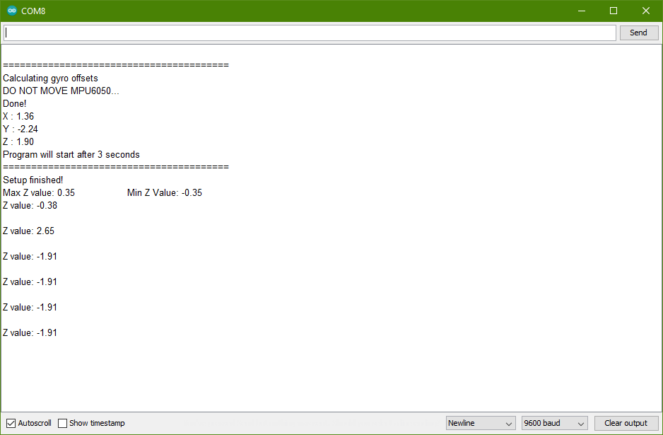
Figure 5. Screenshot of the serial monitor when using the vibration detector.
Problem 5: Use the joystick of the Arduino Elegoo kit to control
the speed and rotation direction of the NEMA stepper motor. Use both
wire connections and wireless connections between the joystick and the
NEMA motor.
For problem 5 we needed to use the joystick module to control the speed
and rotation direction of the NEMA17 stepper motor. Previously in the
last homework we successfully controlled the rotation direction of the
stepper motor but now speed control needs to be incorporated. We also
needed to implement this functionality using both wire connections and
wireless connections between the joystick and stepper motor. I created
the sketch for the wired connections first because I wasn't sure how I
was going to transmit X and Y values wirelessly just yet. I simply get
the values of the X and Y directions of the joystick every loop cycle.
The Y direction values I use as is and it controls the rotation
direction of the stepper motor with upwards being clockwise and
downwards being counterclockwise. For the X direction I decided to have
it control the speed of the stepper motor. I do this by modifing the
delay between the stepPin being set to HIGH then LOW (which moves the
stepper motor). A delay with the range of 0 us and 1023 us didn't
function very well at the lower values so I decided to map the X values
on a range from 100 to 1500. So then when moving the joystick in the
left X direction, the stepper motor would be pretty fast without the
issues I had before.
For the wireless design I used the Open-Smart 2.4 GHz transceivers used
previously and was able to reuse the code written for the wired
version. The main thing I had to figure out was transmitting both X and
Y values. I accomplished this by converting the read values of the
joystick to a string and concatenating them together in this format: (x
value),(y value). This entire string was then transmitted. On the
receiver side, I reused code from last assignment with the modification
that if a comma character (',') was detected, I then converted the
message up to that point into an integer and set my motor speed
variable to its value. I then reset the incoming message string and
continued reading the transmitted string. Now if the new line character
('\n') was detected, that value was used to set my direction value
variable. My motorSpeed and directionValue variables were then used to
control the NEMA17 stepper motor operation in the same way as the wired
design. I noticed I got significantly higher Y values when the joystick
was at rest so I had to modify that part of the code but other than
that the wired design code was reused almost exactly. There is an issue
with stepper motor at higher speeds that I am not sure how to resolve.
This can be seen in the video when demonstrating the motor speed
control functionality, the stepper motor will sometimes stall. A slow
transition from the slower motor speeds to the faster motor speeds does
seem to help.
Problem 6: Implement rotary encoder Algorithm II on your UNO board.
In problem 6 we needed to implement Algorithm II from the slides on the rotary encoded seen during lecture.
Algorithm II functions like this: Counter Clockwise: When A changes
from LOW to HIGH, B is HIGH. When A changes from HIGH to LOW, B is LOW.
When implementing this Algorithm I checked on the status of A, which
was the DT pin on the rotary encoder. I then set the value of B based
on whether A was rising edge or falling edge. I also printed the value
of B to serial so that I can see its value using the Serial Plotter in
the Arduino IDE. The video of the rotary encoder in action is shown
below.
Conclusion:
I enjoyed gaining experience using the different
sensors and actuators in this assignment. My favorite part was figuring
out how to transmit two values using the Open-Smart 2.4 GHz
transceivers as well as creating the vibration detector since it was
pretty open-ended on how we got these designs implemented. The sketches
for this assignment will be uploaded onto the server in a sketch folder
under HW6 as well. I enjoyed learning about the Wheatstone bridge since
strain gauges are something I will be applying to my senior seminar
project, I also was happy to see the ultrasonic distance sensor
functioning since I had heard that its capabilites weren't very good.
It seemed to function well for me as long as it was focused on the soda
can. I saw poorer results when trying to use my hand and pointing the
sensor at myself sitting at my desk.