CE 432 Robotics II Fall 2021
Joystick/Stepper Motor Tutorial
Sean Eaton
smeaton@fortlewis.edu
Joystick/Stepper Motor Tutorial
Introduction:
In this homework we were tasked with understanding how to use a
joystick module with an Arduino, understanding how to use the
Open-Smart 2.4 GHz Transceiver, and understanding how to use the NEMA17
Stepper Motor. Task 1 focused on the joystick module and seeing results
in the Serial monitor. Next the Open-Smart 2.4 GHz Transceiver was
incorporated to wireless transmit joystick readings from one Arduino to
another. Finally boths aspects of the previous tasks were used to allow
for remote control over the NEMA17 Stepper Motor.
Task 1: Joystick Test
For task 1 an Arduino and a joystick
module were used to collect the X and Y position values of the
joystick. The joystick itself is shown below in Figure 1. The way it
works is by using two potentiometers in addition to a switch. One
potentiometer tracks the position on the X-axis with values ranging
from 0-1023, the other potentiometer tracks the position on the Y-axis
with values from 0-1023 also. There is also a switch input that is
triggered by pressing down onto the joystick, the pushbutton can be
seen in Figure 1 below. The output range of 0 to 1023 is thanks to the
10-bit resolution of the Analog to Digital Convertor included within
the Arduino Uno board. Since there are 10 bits, the resolution can be
calculated by finding the value of 210
which is equal
to 1024. There must be a total of 1024 numbers then, and when including
0, we end up with the range of 0-1023.
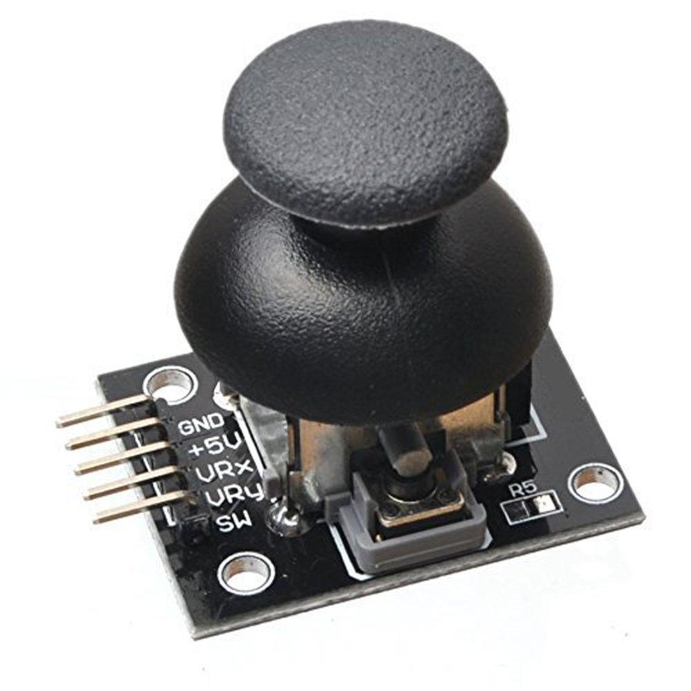
Figure 1. The type of joystick module used.
The
joystick wiring was completed as specified by the schematic diagram
shown in the tutorial. GND was connected to GND, +5V to 5V, VRx to
Analog Pin 1, and VRy to Analog Pin 0.
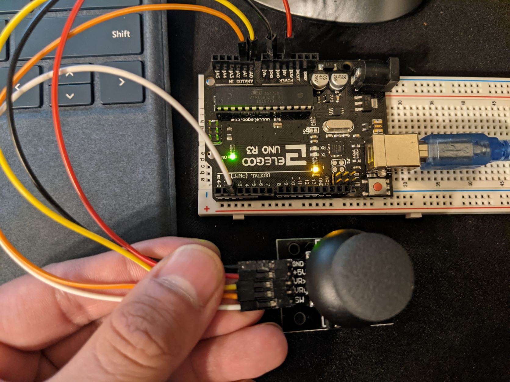
Figure 2. Joystick module physically wired to the Arduino Uno.
After
physically wiring the joystick, the example test code was uploaded to
the Arduino where a variety of different outputs were obtained by
moving the joystick and pressing down on it. The readings can be seen
below in Figure 3. The default position of the joystick is the center
so readings end up being around 500 since half of 1023 is about 511.
There is some slight fluctuation since the joystick and potentiometers
are physical devices and so the 500 readings below are approximately
the center. When tilting the stick to the edges the readings will
report values like 0 and 1023 which are the mininum and maximum values possible.
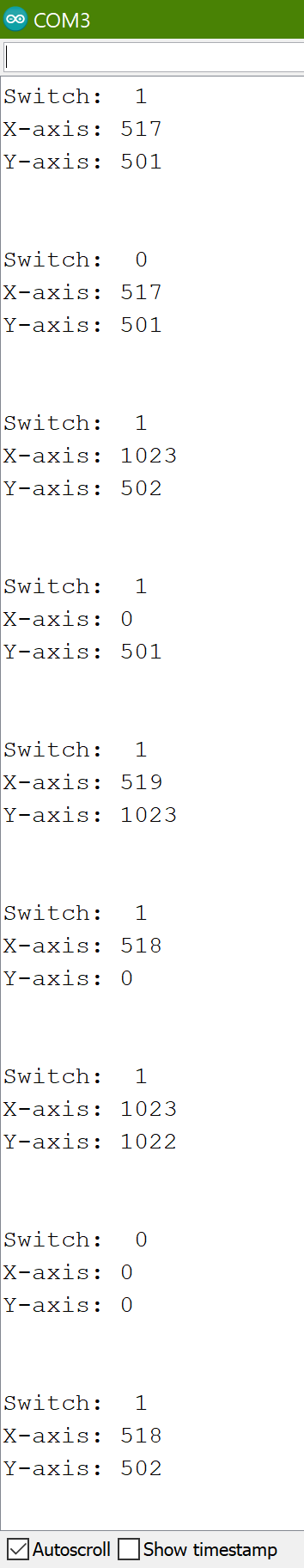
Figure 3. Serial monitor displaying outputs of the joystick module.
Task 2: The Open-Smart 2.4 GHz Transceiver
For task 2 the Open-Smart 2.4 GHz Transceiver was introduced. This
device is able to communicate with another device wirelessly with
minimal setup. All that is needed is to power them on and control what
is being transmitted or when to read using an Arduino. Another
important thing to note is that the RX and TX ports on the transceivers
are being controlled via digital pins 2 and 3 using a library called
SoftwareSerial. The Arduino Uno does have physical RX and TX serial
ports on the digital pins 0 and 1 but these are not used for the
transceivers. This is because they are being used by the USB cord when
uploading code and using the serial monitor in the Arduino IDE.
An
initial test was conducted to verify the transceiver functionality. A
simple for loop transmitted the numbers 0-5 repeatedly, the results can
be seen in Figure 5 below. When viewing what is being received on the
Arduino Serial Monitor the readings get these large white spaces
inbetween them which is why Figure 5 looks the way it does.
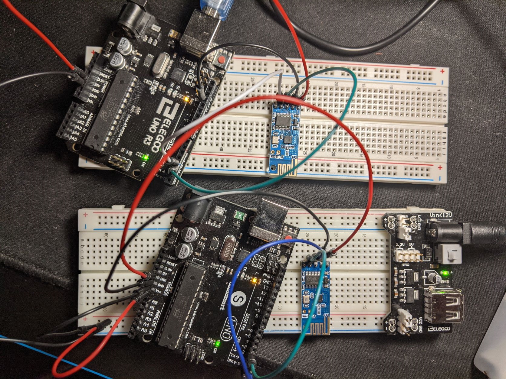
Figure 4. Physical wiring for the transceivers.
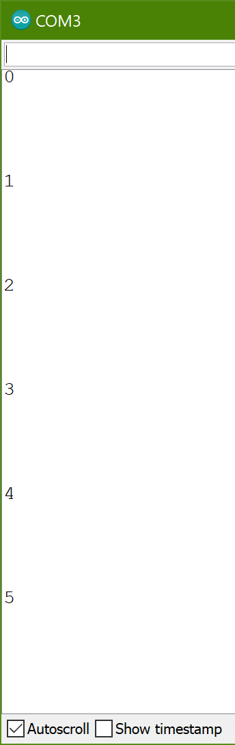
Figure 5. Serial monitor showing the initial transceiver test results.
After verifying the transceiver functionality, the joystick module
was incorporated and its Y-axis readings were transmitted. Figure 6
below shows the physical wiring for this portion of the task. The
Arduino with the joystick connections is transmitting the readings
using the Open-Smart 2.4 GHz transceiver. The Arduino that is only
connected to the transceiver is the receiving end and is printing those
readings to the serial monitor shown in Figure 7.
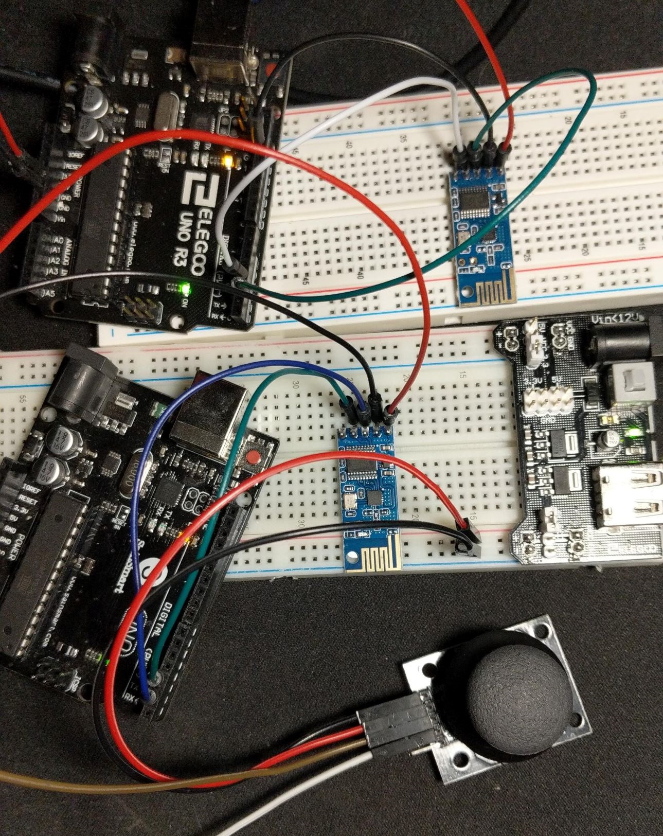
Figure 6. Physical wiring connections for the joystick and transeiver test.
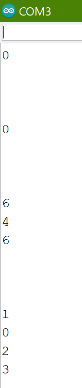
Figure 7. Receiver readings displayed on the serial monitor.
As
you can see in Figure 7 above, the formatting for the data is pretty
weird. In order to fix this additional code can be used to find where
the newline break occurs. The data is being transmitted as a string and
so the end of the string can be detected by looking out for "\n" which
denotes the end of the message. After making this fix the Serial
Monitor is able to display incoming messages in a more readable format
as well as convert the incoming message into an integer number,
something that is necessary if we want to control the stepper motor
with this method.
Figure 8 below shows the fixes to the serial
monitor formatting. Lines that begin with "Received" are finding the
end of the message by looking for the newline character, "\n", and
directly printing that string. Lines where there is just a number are
points where the string has been converted to an integer, this integer
is then printed to the Serial Monitor as is so verify the original
string and its integer conversion is correct.
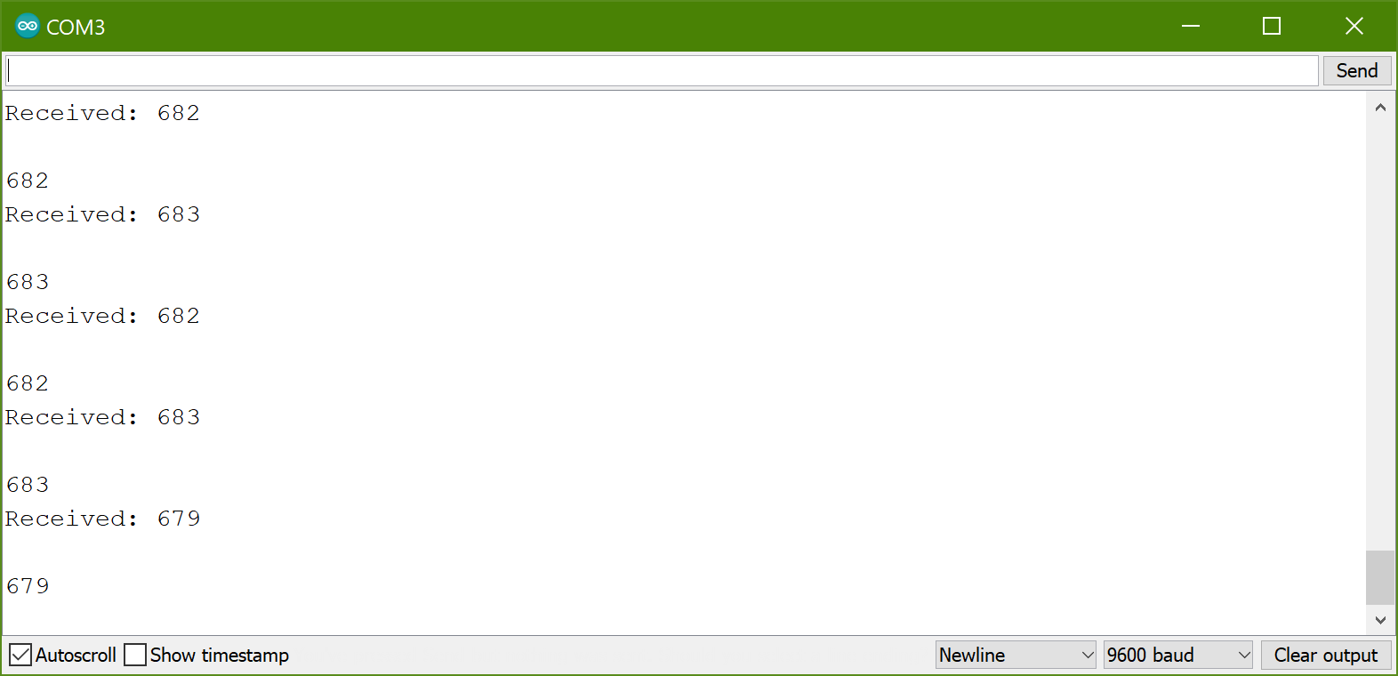
Figure 8. Serial monitor displaying readings in a readable format along with showing successful integer conversions.
Task 3: Remote Controlling the NEMA17 Stepper Motor
For the final task, we needed to remotely control the NEMA17 Stepper
Motor using the Open-Smart 2.4 GHz transceivers, two Arduino Unos, and
the joystick module. After reading a short tutorial on how the wiring
should be done for the NEMA17 Stepper Motor as well as the A4988
Stepper Motor Driver, a short test was conducted to verify the stepper
motor functionality. All this test did was rotate in one direction,
stop, and then begin rotating in the opposite direction before
repeating. After verifying stepper motor functionality, the example
code to allow remote controlling of the stepper motor was uploaded to
both Arduino Unos.
In the video below you can see that the
stepper motor is being controlled via the Y-axis readings of the
joystick module. Some adjustments to the code were necessary due to the
joystick module consistently outputting values near 650 for the default
position of the joystick. This was a large increase over the values
near 510 I was getting in Task 1. It was also necessary to use the LiPo
batteries because the 5V powersupply used in previous homeworks could
not supply enough power to the NEMA17.
Conclusion:
I enjoyed learning how to use the Open-Smart 2.4 GHz transceivers in
this homework as well as the Bluetooth modules we initially were asked
to use. I learned more about how serial ports can be used thanks to
this homework. The Bluetooth modules were pretty cool, they allowed me
to send serial commands to the Arduino using my smartphone. I also
liked how the previous tasks built upon one another, the first being
how to use a joystick module, next was transmitting those readings
wirelessly, and then finally putting those together to do something
more useful like controlling a device remotely. The transceiver setup
was also very simple and it gave me ideas of how they can be used in
different projects.