CE 432 Robotics II Fall 2021
ESP32-CAM Practice - Take Photos
Sean Eaton
smeaton@fortlewis.edu
ESP32-CAM Practice - Take Photos
Introduction:
In this second tutorial we were introduced to
various different methods of taking photos available to the ESP32-CAM
in addition to using a micro SD card. They ranged from taking a photo
once every 10 seconds, then using a pushbutton, to using a web server,
and even using a Telegram bot. Along with these different methods, the
format of the photo filename was modified to provide date and time
information. The web server functions were also expanded upon. At first
the webserver functioned as an online push button basically before an
SD card management function was added and later a button to email a
photo. The final task introduced how a Telegram bot can be used to take
photos and control the flash of the ESP32-CAM.
Task 1: Take some photos by itself
For task 1 the ESP32-CAM was
programmed with the provided example code that takes a picture every 10
seconds and saves it to the micro SD card. The code was easy to
understand and we needed to change the quality of the JPEG picture to
40 to ensure pictures were of a decent quality for viewing. I used a
4GB micro SD card and a reader I had laying around for this homework.
Figure 1 below shows the 5 pictures taken for Task 1. The first picture
has a strange error that has no fix currently.
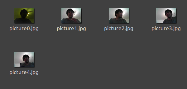
Figure 1. The 5 task 1 pictures that were saved to the micro SD card.
Task 2: Customize the photo names
For task 2, additional code allowed the picture file names to contain
the date as well as the time the picture was taken. The ESP32-CAM is
able to obtain what time it is by connecting to a NTP server. Some
modifications to the code were needed because the server send GMT time
by default. In order to get MST 6 hours must be subtracted. There is a
section in the code for a GMT Offset value in seconds, so this was set
to -6 * 3600. There is also an offset for daylight savings time but
should remain zero at this time of the year.
As you can see in Figure 2 below, the file names have the correct date and time for when the pictures were taken.
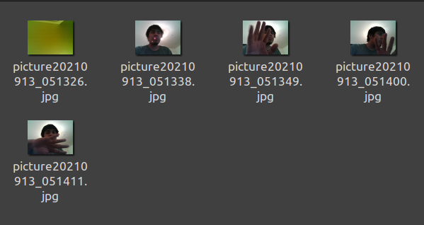
Figure 2. The 5 task 2 pictures that have correct date and time file names.
Task 3: Take photos with a push button
For task 3 a push button needed to be connected to GPIO 16. A software
debouncing solution is implemented in the example code so that the
button must be in a stable state after 50 ms to activate the ESP32-CAM
camera. The push button defaults to a HIGH state and when the button is
pressed it will go LOW.
I unfortunately had issues getting good pictures using the example
code. For the push button connections I followed the circuit diagram
exactly, even connecting the button to 3.3V and using a 10k Ω
resistor. I also tried using 5V, connecting the grounds together, and
using 3.3V from my power supply in case that was the problem but I
didn't see any improvement in the results. My hardware connections are
shown below in Figure 3.
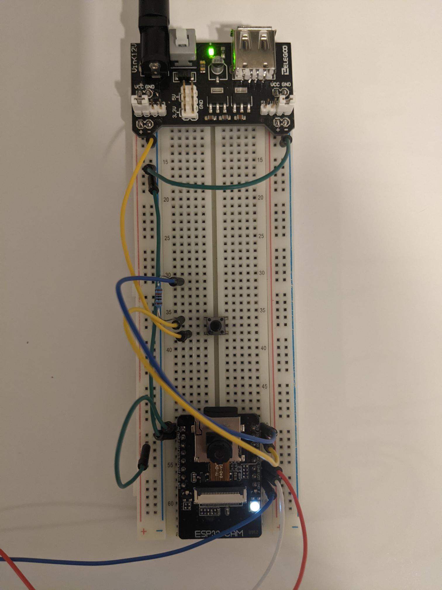
Figure 3. Hardware connections for using the push button.
When completing this task I had errors in the resulting pictures. Most
of the picture wasn't able to be seen and was made up of gray pixels.
Sometimes the file became corrupted as shown with picture 5. I
originally thought I had ruined the ESP32-CAM board or the camera
module somehow with my push button wiring but this wasn't the case. I
experimented with the power supply wiring in case the ESP32-CAM wasn't
receiving enough power but the pictures still came out like this.
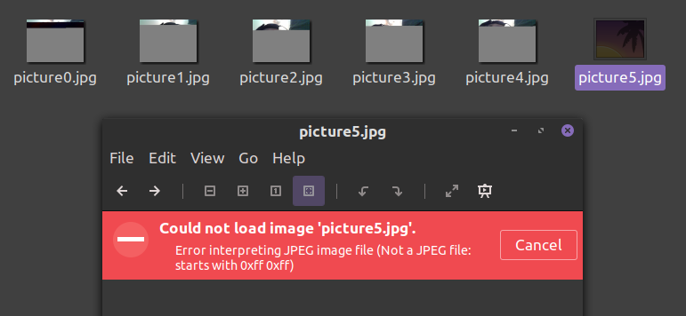
Figure 4. Contents of the micro SD card when taking pictures with the push button.
According to the serial monitor the ESP32-CAM was functioning as
expected. The camera module and micro SD card module were able to be
set up successfully. Button presses were recognized and the pictures
were saving. This was also a good attempt, prior to this the push
button would not be recognized a majority of the time. I'm not sure why
this task had so many issues since a push button was successfully used
in homework 1.
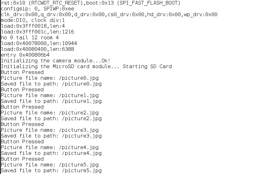
Figure 5. Serial monitor output when taking pictures using the push button.
Task 4: Use a web server to take pictures
For task 4 some new libraries needed to be installed in order for the
example code to function correctly. These libraries were the
ESPAsyncWebServer library and the AsyncTCP library. The provided
download links in the ebook were used to install these libraries.
Relevant sections of the code such as image quality and network
credentials were edited prior to uploading to the ESP32-CAM.
In order to take pictures using this web server you have to navigate to
the IP address shown in the serial monitor, for me it was 192.168.1.53.
You then need to capture a photo and then refresh the page to see it. A
rotate button is also included so that the ESP32-CAM's rotation doesn't
matter as much.
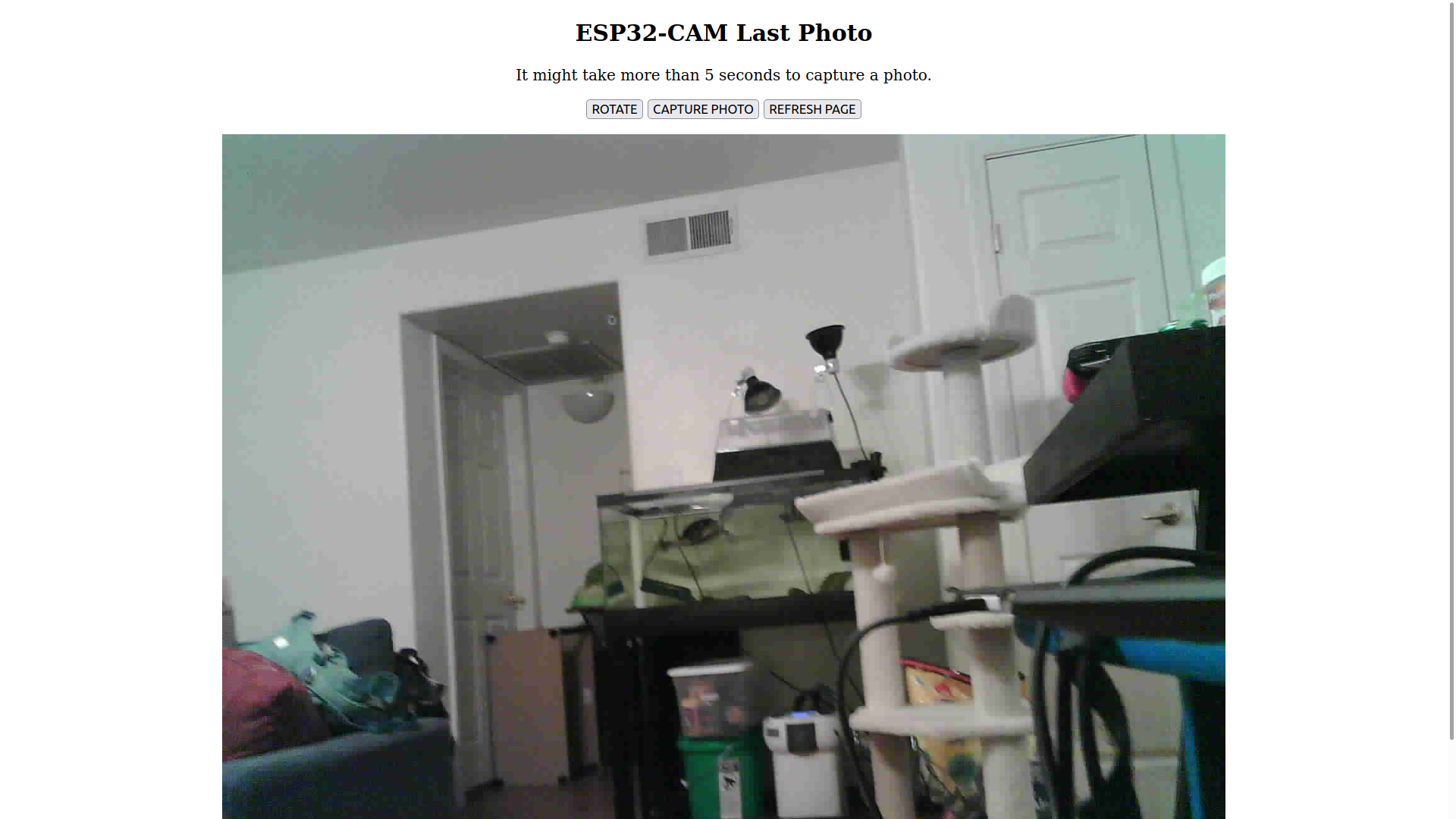
Figure 6. Result of using a web server to take a photo of my living room.
Task 5: Web Server SD Card Photo Manager
For task 5 a manager for the micro SD card was added to the web server
example code. The ability to capture photos is retained along with the
added ability to view and delete the contents of the micro SD card. The
date and time used for the photo file names should also be implemented
as well. Using the calculations from task 2 I was able to set the
correct time for my photo. I had taken photos previous to this so the
first two are incorrect but the third and latest photo has the correct
date and time as shown in Figures 7 and 8. The second photo uses an
incorrect GMT offset and the first photo uses no GMT offset.
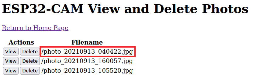
Figure 7. The red boxed photo correctly reports the date and time the photo was taken.
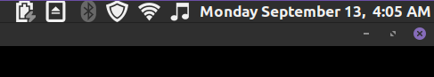
Figure 8. Screenshot of my computer's current time when taking the third photo.
Task 6: Take photos and send notifications
For task 6 the functionality for the ESP32-CAM to send an email with
the photo taken was added. This new example code would take a photo
shortly after the ESP32-CAM was turned on. In order to do this the
ESP32 Mail Client library had to be installed. For some reason, when
using the most up to date version of this library I was receiving an
error that there was no member called timesstamp in this line of code:
localtime_r(&result.timesstamp, &dt);
I thought maybe there was typo and changed it to timestamp, but this
led to another error with the types involved. After researching how
this error could be fixed I found that the most up to date version of
the library must've changed something and it isn't compatible with the
exmaple code. The solution was to install v1.1.6 of the library using
the Arduino Library Manager rather than verison 1.5.0 which the
textbook link directs to. Other versions may work but v1.1.6 was the
recommended version I saw so I went with it for simplicity.
In addition to having to install this library, a new email account had
to be created specifically for the ESP32-CAM to email me notifications.
I decided to make a gmail account since it was supported by the example
code by default. I edited the code to include the login credentials, my
personal email, and uploaded it to the ESP32-CAM. As shown in Figure 9
below, the ESP32-CAM was able to successfully send me an email of the
photo that was taken.
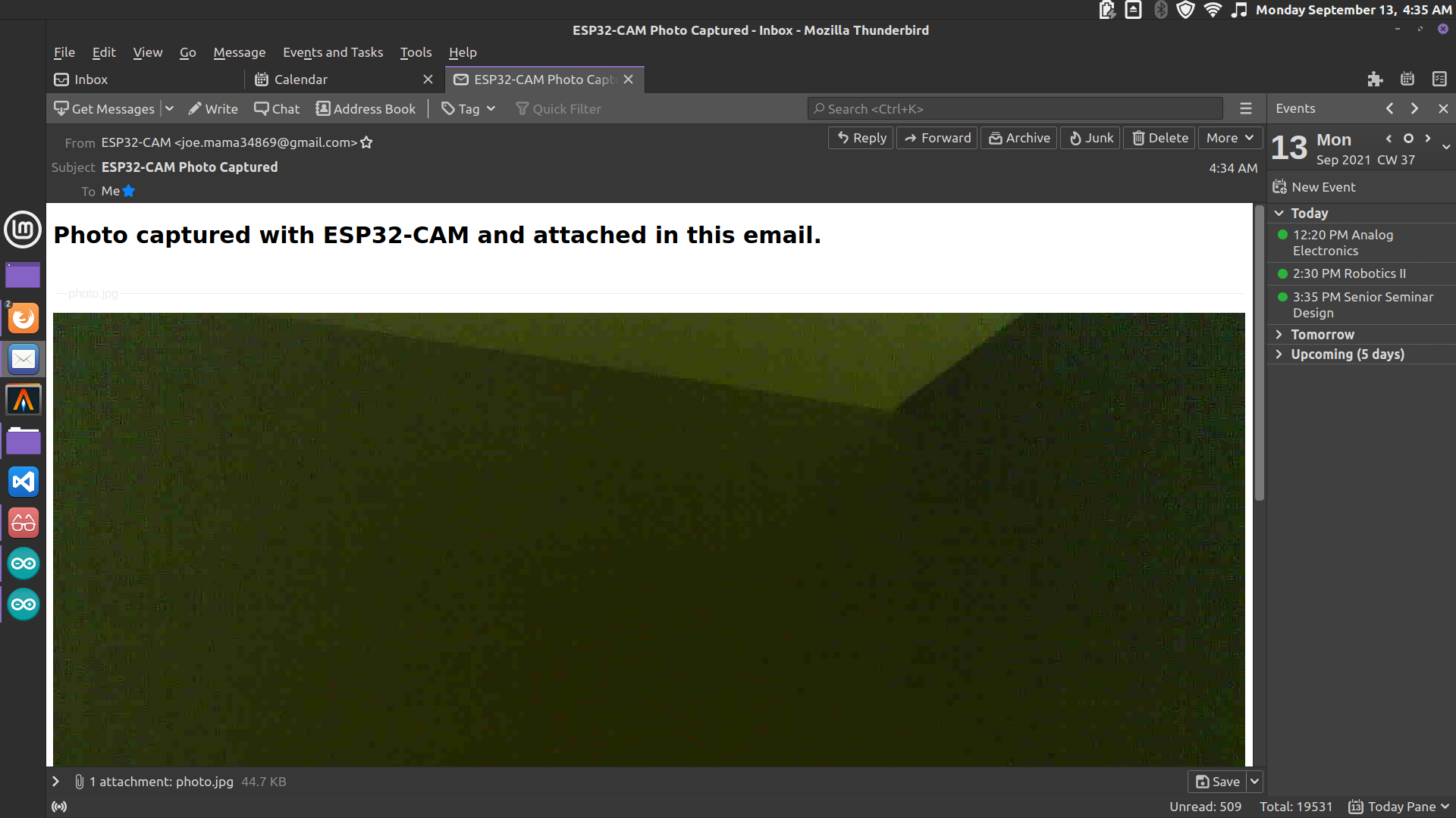
Figure 9. Screenshot of the email and photo sent via the ESP32-CAM board.
Task 7: Take photo and email photo with a web server
For task 7, the web server was used once again with the added
functionality of being able to send the photo to in an email. I edited
the code so that my personal email was the default one but there is a
text box at the bottom of the page that can be used to send it to any
other email. To send the email you have to click the email photo
button. Figure 10 below shows the web server along with the serial
monitor showing that the photo was successfully emailed. Figure 11
shows the email I received.
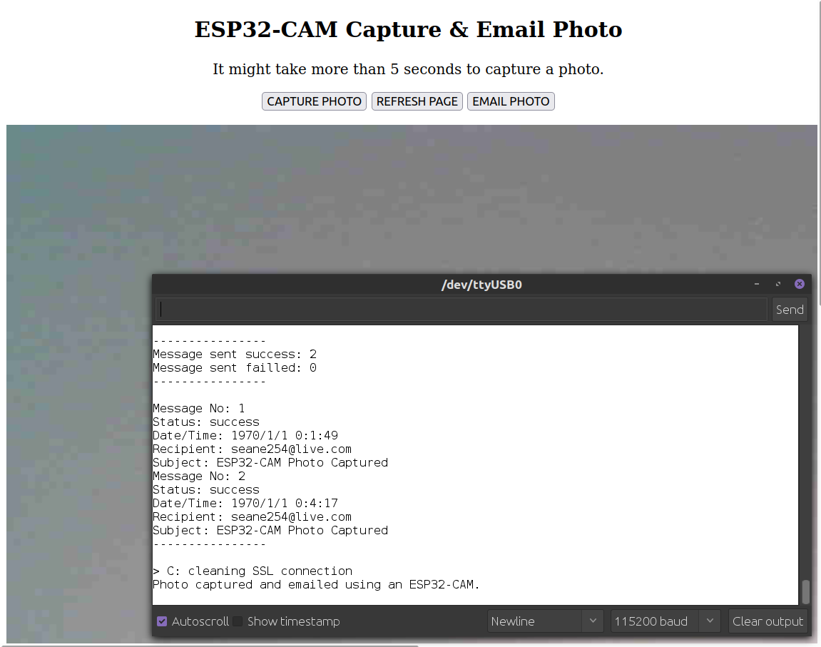
Figure 10. Screenshot of the web server along with the serial monitor displaying successful results.
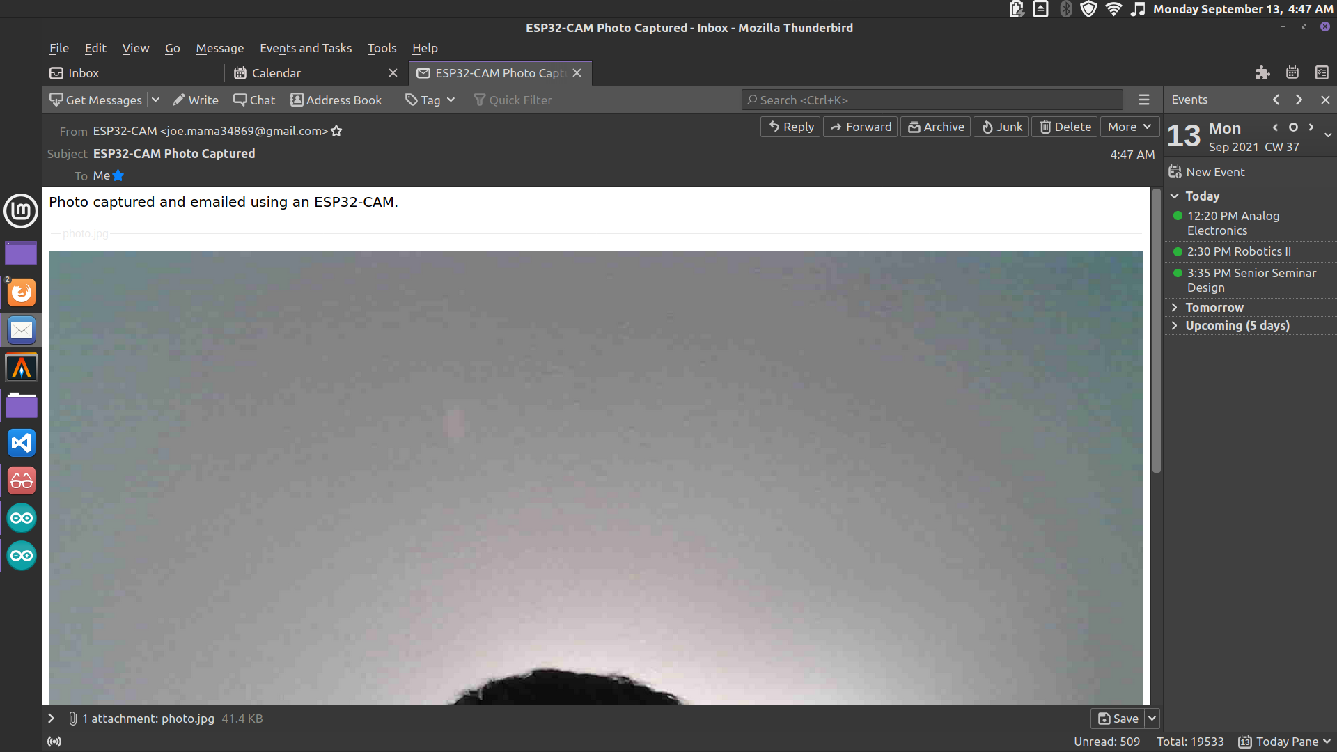
Figure 11. Screenshot of the email and photo sent by the ESP32-CAM web server code.
Task 8: Take and send photo to Telegram app
For task 8 the Telegram app was used to control the ESP32-CAM. In order
to do this I had to create a Telegram account for this tutorial. In the
Telegram app you are able to search for the 'botfather' account which
creates a bot for you to use for whatever you want. After doing this
the BOT token needs to be saved for use in the example code. After this
another bot called 'IDBot' was used to get the chat ID for my own
account. These are necessary for getting the example code to function
correctly. After editing the code to connect to my WiFi and changing
the JPEG quality to 40, I was able to control the ESP32-CAM using the
Telegram app. Figure 12 shows that I am able to turn on the flash using
Telegram. Figure 13 shows that I am able to take a photo and see the
results in the Telegram app.
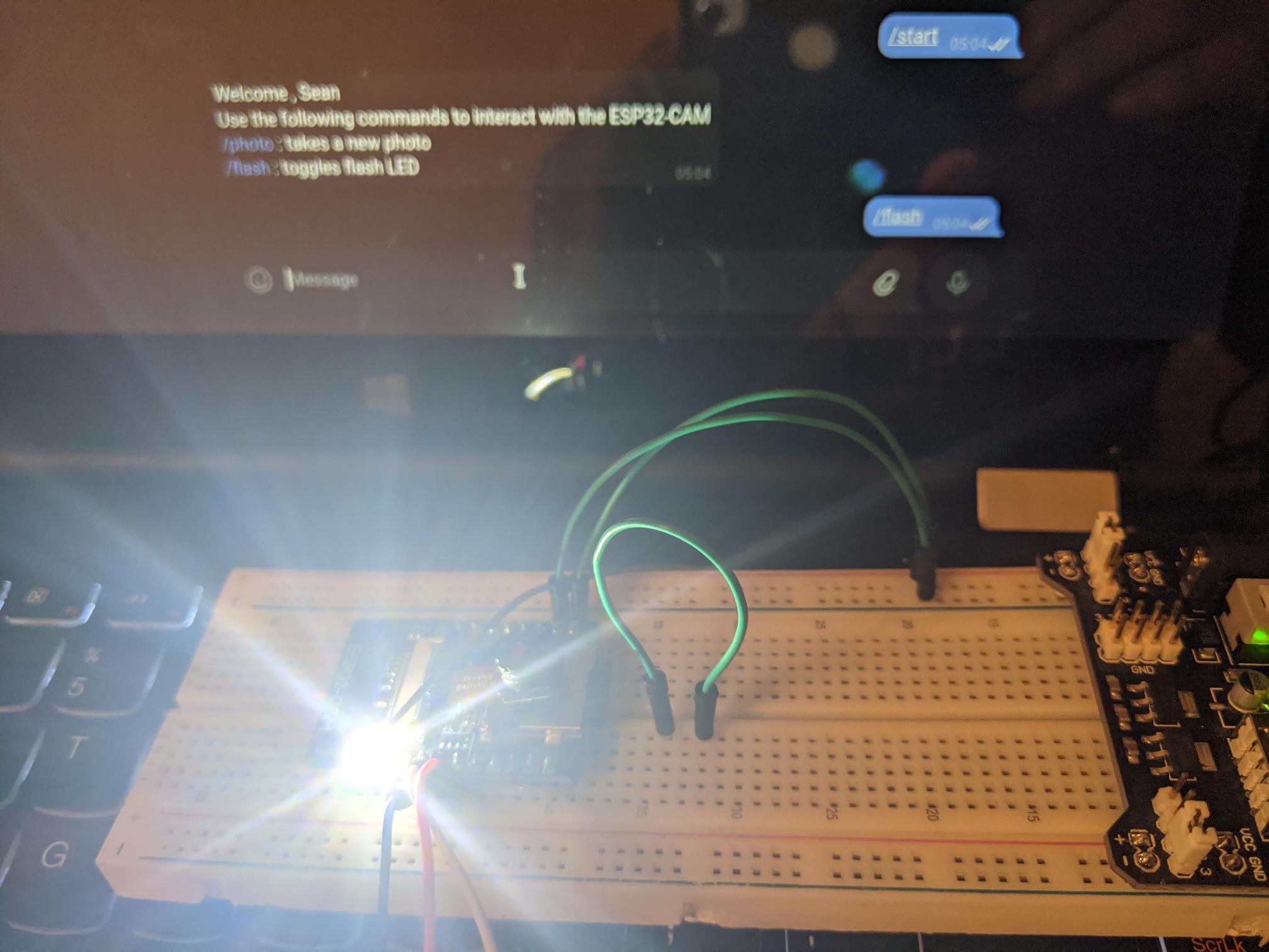
Figure 12. Turning on the flash using the Telegram app.
Figure 13. Using the Telegram app to take a photo on the ESP32-CAM.
Conclusion:
This tutorial was very interesting to me, I wasn't
aware that the ESP32-CAM was able to be controlled remotely using so
many different methods. I think the email notifications and the
Telegram examples would be the most useful since the camera can be
controlled remotely so easily. I also have never used the Telegram app
and I am interested in seeing how it can be used in other projects now.
It is unforuntate that task 3 wasn't able to function like it waws
supposed to, I am interested in why it wasn't working exactly but
I wasn't able to figure out what was going on. I also ran into a brown
out detection error when attempting to complete task 4 even though the
brown out detection was set to 0. I don't know exactly why this was
happening. My only idea is that it might've been caused by the PCB
protoboard I was using due to the 5V power supply not connecting
directly to the ESP32-CAM board. I was able to get rid of the brown out
error by using the breadboard instead.