CE 432 Robotics II Fall 2021
Self Balancing Robot Project
Sean Eaton
smeaton@fortlewis.edu
Self Balancing Robot Project
Introduction:
For the final project of Robotics II we were
tasked with creating a self-balancing robot car using our experience
with the NEMA17 stepper motors and incorporating a MPU6050 which is an
accelerometer and gyroscope sensor. This robot was split into two
parts, the first of which dealt with learning how to use the MPU6050.
We were required to learn how to use the I2C protocol to interface with
the MPU6050 and become familiar with reading from the MPU6050's
relevant registers. During this process a frame for the robot also had
to be constructed using sheets of plexiglass and threaded screw rods.
These were cut to size and assembled into a frame capable of securing
the stepper motors and Arduino circuit. In part two the interrupt
service routine (ISR) of the ATMega328P was introduced as a method of
providing feedback to the stepper motors every 20 us. By doing this the
stepper motors are able to move accordingly in order to self-balance
the robot car. The feedback provided to the ISR is in the form of a
Proportional-Integrative-Derivative or PID controller. Using the
methods used in part one to get accurate MPU6050 values, the PID
controller does further processing to provide an accurate measurement
of the robot's pitch which is necessary to balance the robot.
Self Balancing Robot Part 1:
Due to the class having done portions of part one previously in the semester, the tasks in part one begin at Task 5.
Task 5: Modify the MPU's code to display the raw acceleration data of the X axis.
The
MPU6050's raw acceleration data was displayed by modifying the provided
MPU6050 example code. The Arduino circuit for the MPU6050 is shown
below in Figure 1. The MPU6050 and breadboard were orientated
perpendicularly to the table so that the raw z acceleration of the data
is in the 8000 range as shown in the project's webpage. The raw
acceleration data was printed to the Serial Monitor and can be seen in
Figure 2 below.
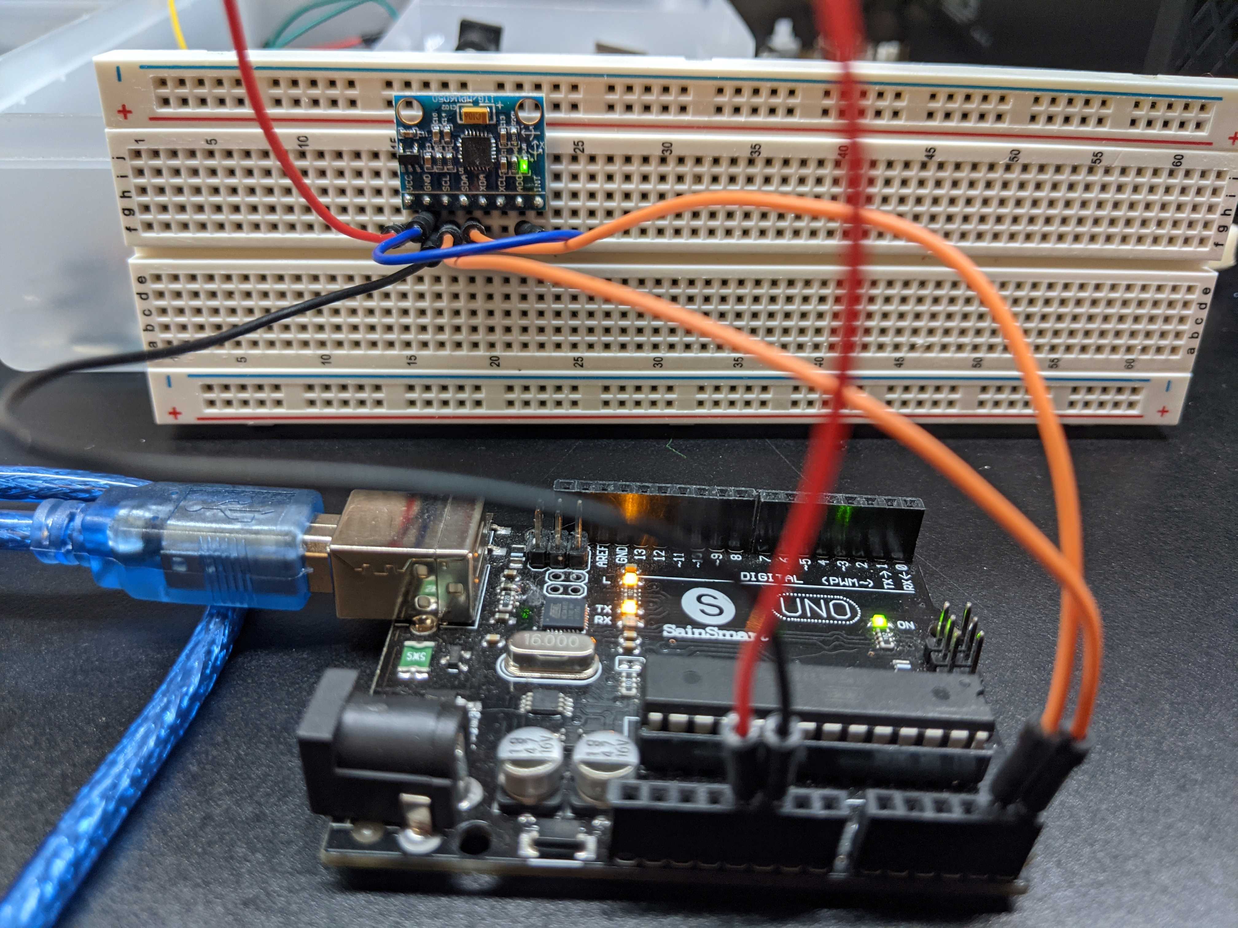
Figure 1. MPU6050 connected to the Arduino Uno.
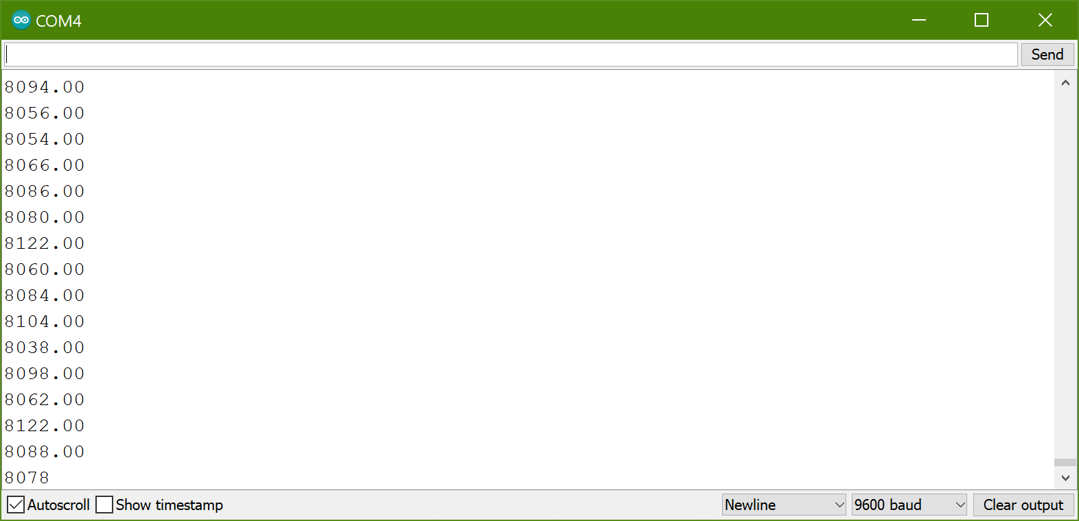
Figure 2. Serial Monitor output displaying raw z acceleration data.
Task 6: Calculate a gyro pitch calibration value and report it to the Serial Monitor.
A
gyro pitch calibration value can be calculated by averaging reported
values when the gyroscope is at rest. This can be done by creating a
for loop and adding together the read values before dividing the sum by
the number of for loop iterations. The results can be seen below in
Figure 3. There is some variation to the values being reported after
calculating the calibration value but its likely due to the scale on
the y axis. On the project webpage the y axis scale is from -6 to 6 so
the variation in reported values looks much smaller.
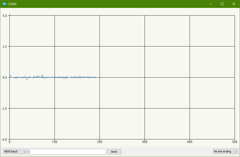
Figure 3. Gyro pitch calibration values after calculating a gyro pitch calibration value.
Task 7: Blink an LED at 1 Hz using a loop timer variable.
A
loop timer can be created by implementing a while loop with the
condition that a certain amount of time has to pass before the while
loop breaks. The loop timer is necessary for implementing a PID
controller so that the change in time can be accurately used. A video
was created to display the LED light blinking on and off every second.
Task
8: Mount the MPU6050 sensor/breadboard on top of the car. Gently lean
the car from 0 degrees to 90 degrees and -90 degrees. Check if you are
receiving 90 or -90 on the serial monitor.
For task 8 we needed to
implement an angle calculator so that the MPU6050's values can be used
to determine the robot car's orientation. This task was also split into
two parts. In part one we were required to calculate the angle using
the gyroscope pitch values in addition to calculating the angle using
the accelerometer in the Z direction values. The accelerometer values
are able to be used to calculate the angle by using trigonometry to
solve for the angle. In part two we were required to calculate the
angle using only the Z accelerometer values.
The
video displaying the use of the gyrscope and accelerometer for the
angle calculations is shown below. For some reason the angle updates a
bit slowly when using this method. When at rest the reported angle is
consistently near zero and when rotating the car forward or backward
the angle adjusts accordingly. Once the angles get closer to 90 degrees
or -90 degrees the reported angle needs to catch up to the car's
position. After waiting shortly the reported angle will then be close
to the expected values of +/- 90 degrees.
Next
is the video displaying the use of the accelerometer only. This code is
based off of the previous code and it turns out to be much more
responsive to changes in angle compared to when the gyroscope was being
used. The reported angle updates to +/- 90 degrees more quickly than
previously. There used to be nan outputs when the robot reached near
+/- 90 degrees rotation. This was able to be fixed by limiting the raw
values to +/- 8192.
Self Balancing Robot Part 2:
Task 1: Complete the simplified version of the project shown in the video demonstration.
For
the first task of part 2 the balancing robot should be implemented so
that it is able to remain upright on its own. I originally tried to
implement the balancing robot by using Joop Brokking's code and
tutorials on his Brokking.net website found here.
It was useful for understanding how the robot works but the best
performing balancing robot mainly uses the example code provided by my
instructor Dr. Li here.
The
self balancing robot uses the previous angle calculation code to
determine the robot's pitch orientation. Using the calculated angle a
PID controller provides feedback on if the robot is currently balanced.
The interrupt service routine (ISR) runs every 20 us to control the
NEMA17 stepper motors. The main configurable part of the code was
adjusting the PID gains for the proportional, integrative, and
derivative portions of the PID output. I also had to make adjustments
to the stepper motor portion of the code so that the stepper motors
were rotating in the correct direction in response to the PID output.
After experimentally tuning the PID gains the best performing balancing
robot can be seen below.
There was also the
option to incorporate joystick functionality and attempting the ramp
test but these tasks were not accomplished in time.
Task 4: PCB design, fabrication, soldering, and testing. One PCB for the joystick remote and one PCB for the robot car.
Another
goal with the self balancing robot project was to design a robot PCB
and remote PCB capable of replacing the Arduino breadboard circuit.
The
first PCB I designed was the balancing robot PCB. The first part
designed was the voltage regulator so that the 12V LiPo battery pack
could supply 5V to the ATMega328P. After this I followed a schematic
for a barebones ATMega328P setup. After this I added the A4988 stepper
motor driver boards and the 2.4 GHz transceivers so I could attach them
using female pin headers. The last part added was the MPU6050 and its
own separate voltage regulator that takes the 5V down to 3.3V for the
MPU6050. The schematic for the balancing robot PCB is shown below in
Figure 4. The board layout is shown in Figure 5.
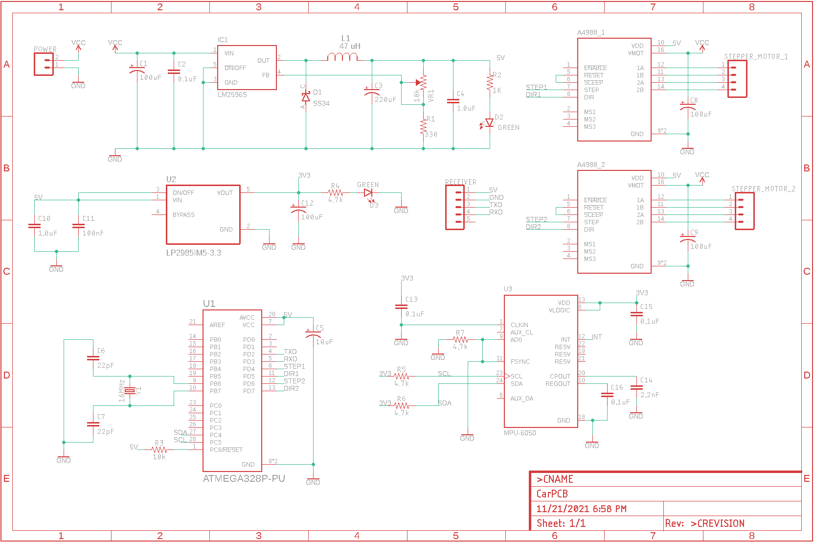
Figure 4. Self balancing robot PCB schematic.
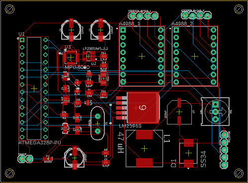
Figure 5. Self balancing car PCB layout.
In
addition to designing the self balancing car PCB, I also designed a
remote controller PCB. The main components are the voltage regulator
for the ATMega328P, a barebones ATMega328P setup, and female pin
headers for the transceiver and joystick modules. This PCB was not the
one manufactured however, my partner, Audra, had her remote control PCB
manufactured.
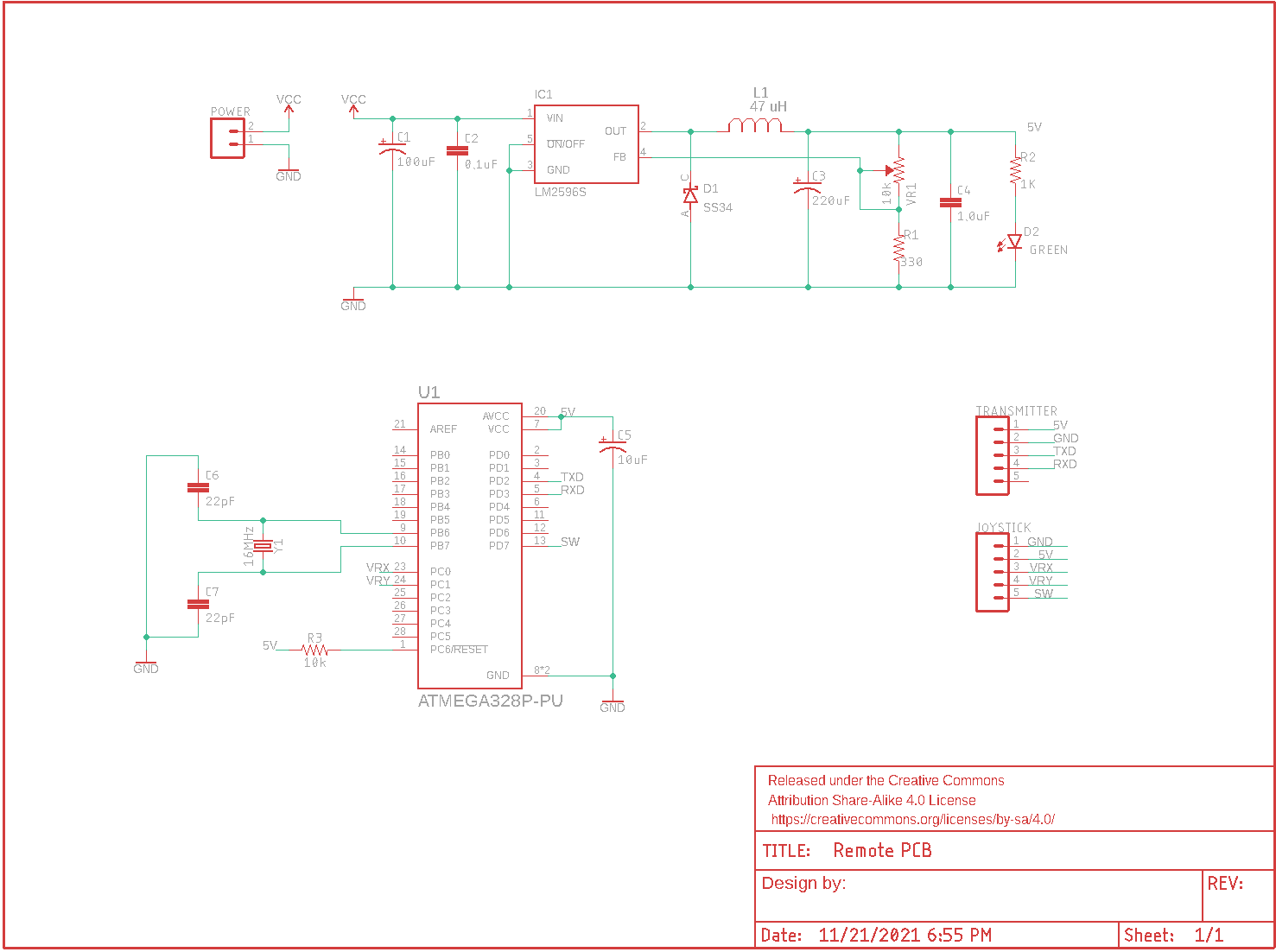
Figure 6. Remote controller PCB schematic.
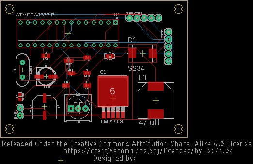
Figure 7. Remote controller PCB layout.
Most
of the componenets for the self balancing robot PCB were soldered on.
Unfortunately the female pin header supply was depleted and so the
headers for the A4988 stepper motor drivers and transceiver couldn't be
soldered on yet. A major improvement upon this PCB compared to the
previous ESP32-CAM PCB is that the correct footprints for the
capacitors and inductor were able to be used.
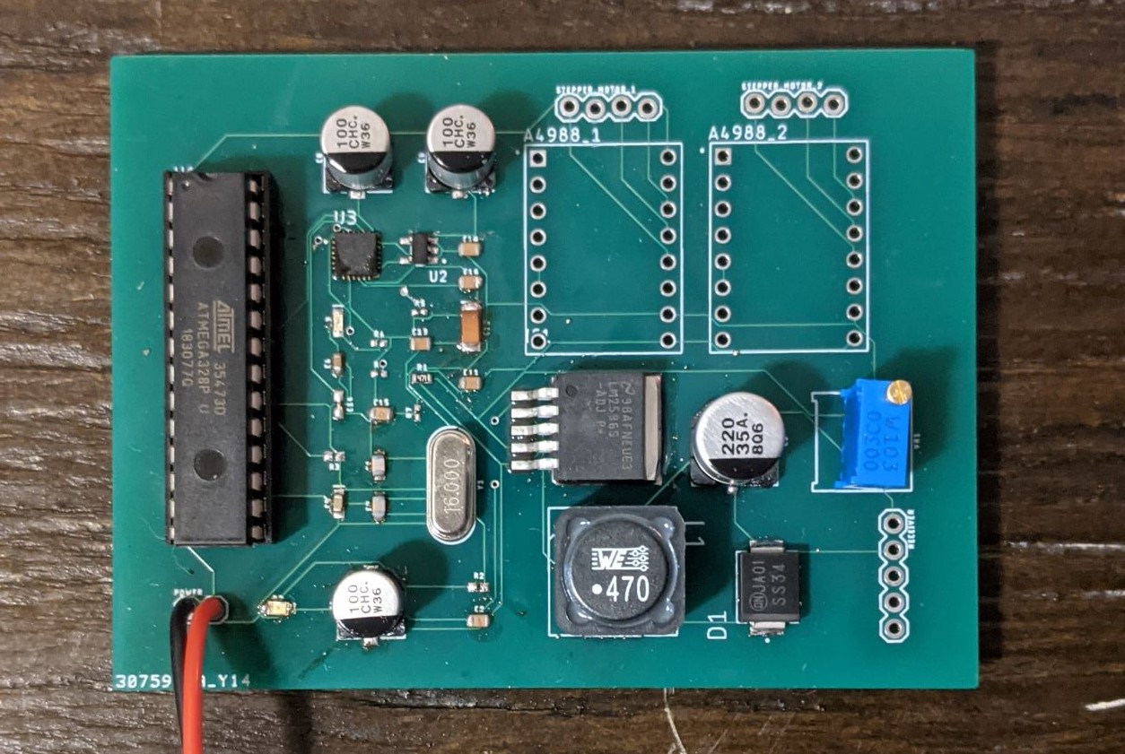
Figure 8. Nearly complete self balancing robot PCB. Appropriate female pin headers still need to be soldered on.
Task 5: Final testing, presentation, and report writing.
For
task 5 all we were required to do was create a presentation of the
final project, demonstrate the robot's functionality, and finish
writing the report.
Conclusion:
I enjoyed working on this final project. Part one
of the self balancing robot was simple and straight forward, I enjoyed
learning about how to use the MPU6050 because I hadn't used one before
without a library handling everything for me. It was interesting
learning how to use the MPU6050 registers to request raw data from the
MPU6050. I also enjoyed studying the provided sample code and the YABR
project when trying to get the robot to balance correctly. I had a
little experience with a PID controller but I was inexperienced at the
time so the provided code was very enlightening for me. I also really
liked designing the PCBs and getting more experience with surface
mounted devices. The tiny resistors I had to use for the MPU6050 and
ATMega328P were definitely the most difficult to solder correctly but I
am happy with the results. There is an issue with the PCB that needs to
be investigated. After completing the soldering I connected the board
to the 12V LiPo battery pack. The LED by the battery connector lit up
as expected but the LED that shows the MPU6050 is powered on did not
light up. The voltage regulator was also not set properly to output 5V
so the MPU6050 voltage regulator was likely destroyed. Later on the PCB
was tested again to check if the MPU6050 would turn on but at this
point neither of the LEDs powered on. In the future the MPU6050
connections should not be completed until the voltage regulator can be
set correctly.
The self balancing robot performance is less than
desirable as well. A majority of the time spent on getting the self
balancing robot working was spent on experimenting with the PID gain
values and the interrupt service routine. I originally followed the
YABR tutorial, which was informative on how the robot works, but it
also included a different PID controller algorithm and different
interrupt service routine. The PID controller and ISR accomodate the
robot rotating and being controllable with a remote controller which is
why I was interested in using the YABR code as the base. After spending
a lot of time on getting the code functioning I decided to use the
example code provided by Dr. Li instead because it was simpler and gave
better results than I had so far. After much experimenting with the PID
gain values the robot was finally able to balance initially but was not
resilient to pushes. The PID controller gains will be continued to be
adjusted to provide better results.
Overall I learned a lot from this project and I was happy to work on it.