CE351 - Microcontrollers 2022 Spring
ESP32 Anomaly Detection Project
Name: Sean Eaton
Email:
smeaton@fortlewis.edu
ESP32 Anomaly Detection Project
Introduction
The purpose of this project
is to replicate the Edge AI Anomaly Detection project by Shawn Hymel
which can be found on the Digikey YouTube channel here.
Anomaly detection is a technique of detecting abnormalities or changes
that may have severe negative effects depending on the system. In a
piece of machinery an anomaly may lead to thousands of dollars of
damage to the machine itself or to the things being manufactured such
as in the case of a robotic arm tasked with a role in vehicle
manufacturing. An anomaly causing the robotic arm to make mistakes in
its movements could break the robotic arm or cause damage to the
vehicle. In part I Shawn Hymel details how data can be collected using
an ESP32 development board, an accelerometer, and a remote server on a
local network.
Task 1:
For the first task the ESP32
needed to run a program capable of connecting to a server, reading
accelerometer data, and transmitting that data to the server. Shawn
Hymel provided an example Arduino sketch that was able to be used with
some modifications. Hymel is using a different ESP32 development board
and a MSA301 3-axis accelerometer breakout board which required some
code adjustments in order to allow the usage of the MPU6050 6-axis
gyroscope and accelerometer breakout boards available to us. The
network SSID, password, and hostname IP addresses also had to be
defined in the Arduino sketch. The hostname IP address can be found by
running the 'ipconfig' command in a command prompt on a Windows PC. The
IPv4 Address is the IP address needed for the Arduino sketch.
Instead of using the Adafruit_MSA301 and Adafruit_Sensor libraries I
opted to use the MPU6050_tockn library that I have had success in using
for other projects. The relevants parts of the code reading the MSA301
sensor were then replaced with code reading the MPU6050. There is no
built in LED on the ESP32 DevkitC V4 development boards we have been
using so discrete LED was used instead. The only additional library
that was needed was the ArduinoJson library. The circuit on the
breadboard can be seen below in Figure 1. The SCL and SDA pins of the
MPU6050 were connected to the SCL and SDA pins on the ESP32 development
board. These were GPIO pins 22 and 21 respectively. The power bank is a
budget one that is able to provide 4700mAh at 5V.
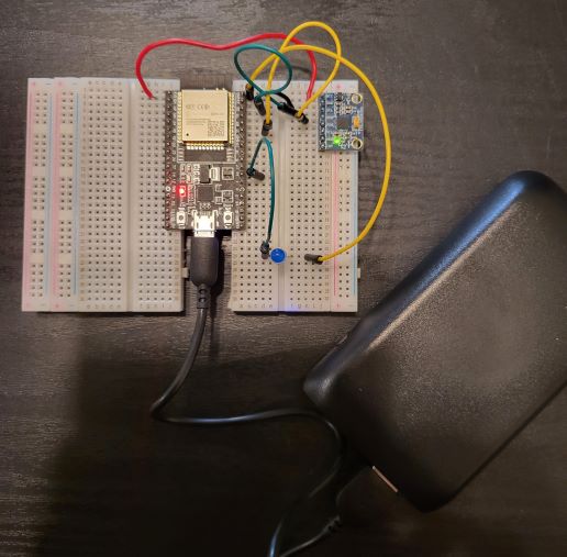
Figure 1. Picture of the circuit implemented on breadboard.
Task 2:
The second task of this
project consisted of running a simple server on my local network so
that the ESP32 is able to transmit MPU6050 accelerometer readings to
it. After transmitting the set of 200 samples the data is saved as a
csv file in the specified folder. This is done using a Python script
also provided by Hymel. There weren't any modifications to the Python
script that were necessary for the code to run although the provided
command needed the folder name, port, and the time for running the
server defined. This command is shown below:
python http_accel_server.py -d <DIRECTORY> -p <PORT> -t <TIME TO RUN SERVER>
The port used in this
tutorial is 1337, which is defined when running the Python script. The
Arduino sketch already has the port defined as 1337 but it could be
changed as long as the Arduino sketch is also changed. Visual Studio
Code was used to execute the Python script. The relevant folder needs
to be opened in Visual Studio Code and then the Run Python File button
can be clicked on. It is after clicking on this button that an embedded
terminal is opened where the command can be entered.
Results:
After getting the server and ESP32 to connect together the ESP32,
MPU6050, and power bank were affixed to a ceiling fan I had access to
using some tape. Figure 2 below shows how this was accomplished. Power
hasn't been connnected to the ESP32 just yet,
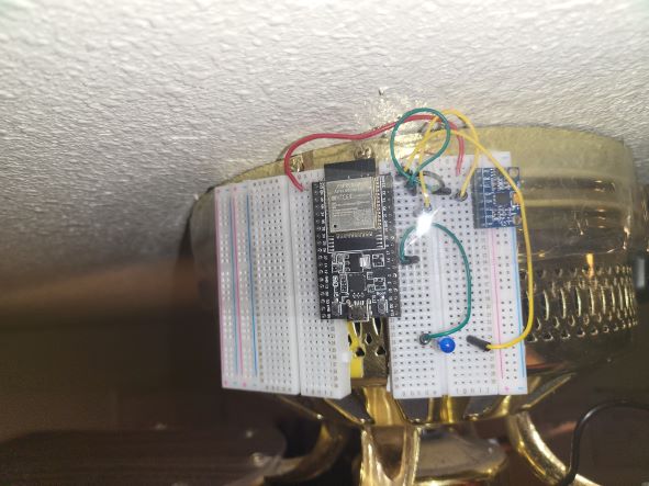
Figure 2. The ESP32 and MPU6050 circuit taped to a ceiling fan.
After this the server was started on my PC. It was important to connect
to my 2.4 GHz Wifi connection because the ESP32 is only able to connect
to connections of that frequency (the 5 GHz connection is not
supported). The server was started first because I thought that it
would be more appropriate for data collection because the MPU6050
needed to run through a calibration process beforehand. This turned out
to be unoptimal however since the first 10 files saved did not consists
of accelerometer measurements when the fan was running. I started the
server then plugged the ESP32 into power. After the ESP32 turned on the
ceiling fan then needed to be turned on, resulting in the first 10 csv
files not being the correct type of data we are interested in saving.
An example of the feedback generated by the Python script running the
server can be seen below in Figure 3. You can see that the csv file
being created is within the 'fastest_speed_01' directory which denotes
the fan speed and dataset number. 535 total csv files were created
using the default 2400 seconds as the time to run the server. For each
csv file 200 accelerometer samples are recorded. These are the
accelerometer values on X, Y, and Z axes. An example of a CSV file can
be seen in Figure 4.
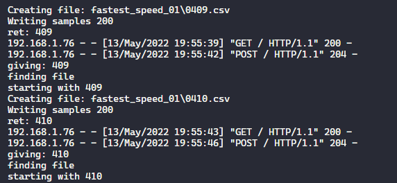
Figure 3. Server script feedback from the Visual Studio Code embedded terminal.
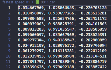
Figure 4. An example of the acclerometer data being recored to each CSV file.
While the ESP32 is connected to the server and transmitting data the
LED is set to blink so that it can be easily seen if the ESP32 is stil
transmitting data. After the server run time is expired the LED ceases
to blink and the server automatically shuts down. An image of the ESP32
during the transmission process can be seen below in Figure 5. It is
important to note that the Python script running the server is not
appropriate for use beyond testing on your own personal network. There
is a lack of security features in the Python code so it is best that it
was limited to my home for a short period.
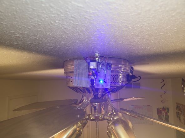
Figure 5. The ESP32 blinks the LED on and off to indicate when data is being transmitted to the Python server.
Discussion
Although this project had the
goal of detecting anomalies this wasn't able to be accomplished in
time. For now the data collection process is able to be conducted and
for future steps a large amount of data is needed for robust anomaly
detection using machine learning. For future work on this project I
would first recommend that one becomes a little familiar with using
Visual Studio Code for Python development to make the process of
getting the server up and running quickly. The next step of Shawn
Hymel's tutorial delves into using Tiny Machine Learning (TinyML) to
accomplish anomaly detection. Large amounts of data will be needed for
feature extraction and for training the machine learning model to
detect anomalies. I enjoyed learning about how a remote data
collection system can be created using the ESP32 and a WiFi connection.
It was nice being able to run the sketch on the ESP32, run the Python
script on my PC, and then wait for data collection to be completed
automatically without any input from myself. I had previously done data
collection for a Junior design course so that a pedestrian detection
neural network could be trained using images from the FLC webcam. In
that project the data collection process was pretty tedious.