CE 351 2020 Fall
Lab 7: Robot Car
Nic Theobald
nstheobald@fortlewis.edu
Robot Car Final Project
Introduction
Controlling
a small car manually, with a tape line, and with sonic distance sensing
are all good demonstrations of reading sensors and controlling real
word objects. This experiment uses a HC SR04 sonic sensor, infrared
sensors, and a IR remote to control the movement of a robot car.
Methods and Materials
Item
Quantity
Arduino IDE
Arduino UNO HC SR04
Robot Car
1
1
1
1
The first step in this experiment was to test the distance
sensor, HCSR04. Then the servo motor was rotated through its 180 degree
range. Then the motors were manually controlled. Then the IR line
tracking sensors were tested.
All of the previous work was then wrapped up in the final robot car. A
remote could be used to direct the car, the line tracking IR LEDs could
be used to make the car follow a line, and the HCSR04 could be used for
obstacle avoidance.
Results
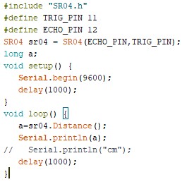
Task 2: Sonic distance sensor
Some basic distance sensing code was written to display the
distance between the sensor and any obstacle. One video shows my hand
in front of the sensor and the other video shows the serial output.
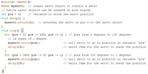
Task 3: Rotating the servo.
Some basic code was written to rotate the servo in its 180 degree range.
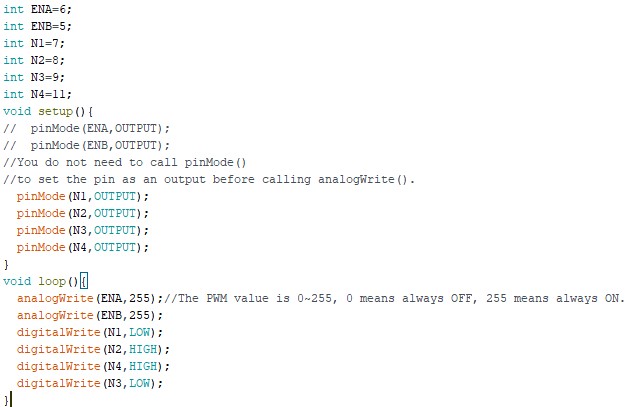
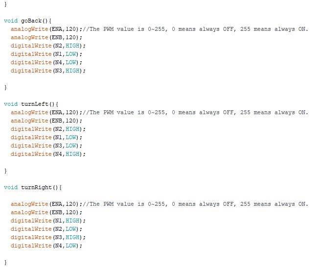
Task 4: Manually Controlling the Motors
The following code was written to control the speed and direction of the motors.
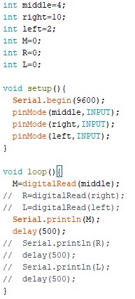
Task 5: Line Tracking
The following code was written to control the motor output given
which sensor detects a line. When one of the IR sensors stops sensing
the IR LED, that means the line is below it. The car is programmed to
try to keep the line under its middle sensor. The location of the line
is also indicated by the red leds on the bottom side of the car.
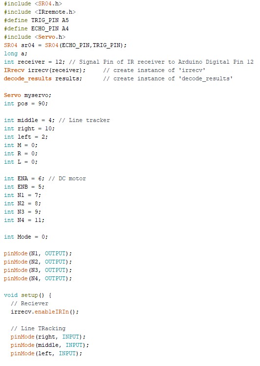
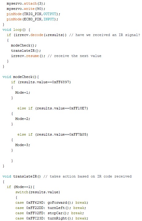
Task 6: Finished Robot Car (In final video)
The existing IR remote code and motor control code was combined
to control the movement of the motors. This mode was initiated by
pressing the number 1.
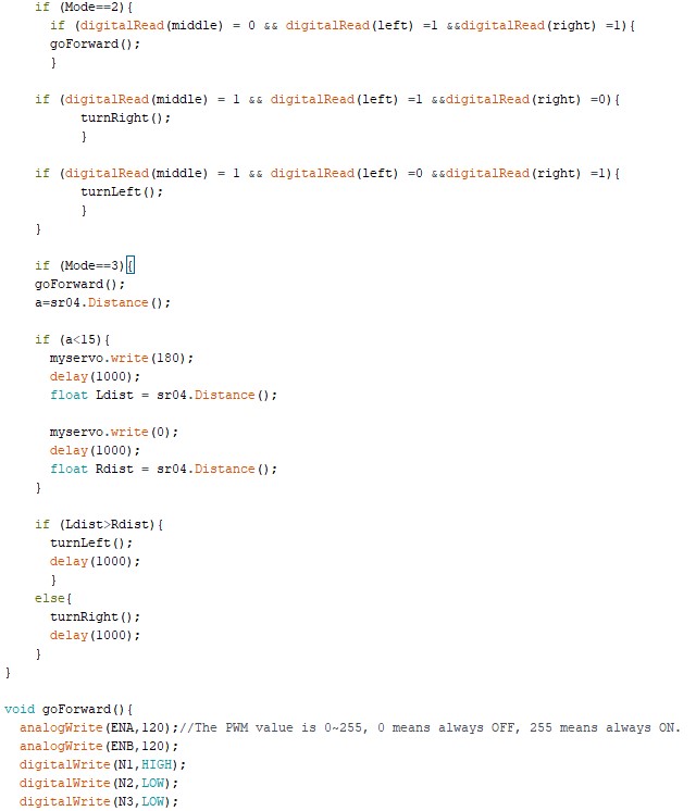
Number 2 initiated the obstical avoidance mode where the car move
forward until the HC SR04 sensor detected a distance of about 15 cm.
Then a function would run that determines the direction with the max
distance. If the direction was right, another function was started to
turn the car to the right. Likewise for the left direction. A possible
improvement to this code would be to back up the car if both left and
right were under 20 cm. The code for rotating the servo and for detecting distance was combined.
The final function of the car, the line
follower, would start the car going straight. If the line was detected
at the right most sensor instead of the middle sensor, the same right
turn function was called to turn the car to the right. Likewise for the
left direction. This code did not work very well and had many problems.
Also, all of my floors are patterned, so the tape didn't do anything. I
know this part of the code worked because the car reacted correctly
when the line was moved left to right under the car. The code from the
line following experiment was used to determine which direction to
turn.
Discussion:
This lab experimented with distance detection, line detection, and
manual remote control. Each method was finally used to control a small
robot car. The car was able to navigate a set track by using black tape
or a sitance sensor. The car was also able to take instructions from a
IR remote. Several improvements could be made to this code. Switiching
between modes didn't always work right. Sometimes the car would need to
be turned off and on again. When the car encountered corners, it would
never get out by itself, so a backup function should have been
implemented. Overall, the car worked pretty well.