How to Make a Mesh/Relay Network out of LoRa Radio Modules
|
| 1) 3x Adafruit Feather M0 w/ RFM95 LoRa Radio-900MHz- Radio Fruit microcontrollers |
| 2) Breadboard |
| 3) DHT11 Temperature and Humidity sensor |
| 4) LCD Screen |
| 5) 1x 10kΩ Potentiometer |
| 6) Jumper Cables |
| 7) LEDs |
| 8) 220Ω Resistors |
| 9) Solid-Core Wire |
| 10) 3.3V power |
| 11) Soldering kit |
| 12) Push button |
Getting the Arduino IDE setup.
1) The first thing to be done
is installing the Arduino IDE and getting
it ready for use with the Feather board. Adafruit has a comprehensive
and easy to follow
walkthrough here.
2) We will also need to install libraries for the sensors and sleeps we will be using, in this case DHT11 Temperature and Humidity sensor. The library for DHT11 can be Downloaded from GitHub here. Adafruit_SleepyDog can be downloaded from here.
Download the Zipped library and extract it your computer. Next drop the
library into the Libraries folder in your Arduino file.
This process can be applied for any additonal libraries you need in a project of your own.
2) We will also need to install libraries for the sensors and sleeps we will be using, in this case DHT11 Temperature and Humidity sensor. The library for DHT11 can be Downloaded from GitHub here. Adafruit_SleepyDog can be downloaded from here.
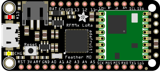
Setting up your Feather Boards
When you recieve your Feather
board it will not have header pins
attached. You will need to solder the header pins to the Feather Board.
There are several ways to attach headers and they can be found here.
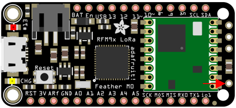
Next up we need to make the Antennas. Depending on what frequency your LoRa is designed for, in our case 900MHz, you will need a specifc length. This can be calculated by Antenna length = 3*10^8(speed of light) / 900*10^6 (desired frequency). For our 900MHZ our length turns out to be 33.3cm. To make the length more reasonable we can make a half qave or quarter wave antenna. To do so divide your length by 2 or 4 respectivly whichever you choose be sure it is the same for the reciever and transmiitter. If you want more info about the Physics involved it can be found here.
So now that we know the length to make a half wave antenna, 16.6cm, lets cut the wire. You can use solid core wire and cut it to length. Next we will solder it to the Ant. Pin. The straighter the antenna the better results you will have. Repeat this for as many Feathers as you need.
Now you Feathers are primed and ready to go.
Next up we need to make the Antennas. Depending on what frequency your LoRa is designed for, in our case 900MHz, you will need a specifc length. This can be calculated by Antenna length = 3*10^8(speed of light) / 900*10^6 (desired frequency). For our 900MHZ our length turns out to be 33.3cm. To make the length more reasonable we can make a half qave or quarter wave antenna. To do so divide your length by 2 or 4 respectivly whichever you choose be sure it is the same for the reciever and transmiitter. If you want more info about the Physics involved it can be found here.
So now that we know the length to make a half wave antenna, 16.6cm, lets cut the wire. You can use solid core wire and cut it to length. Next we will solder it to the Ant. Pin. The straighter the antenna the better results you will have. Repeat this for as many Feathers as you need.
Connection Schematics
Transmitter
We will first
start out with wiring the transmitter red wires are power, blue are
data, and black are ground. The DHT11 Sensor will be used to collect
the data we will be sending. The two LEDs will be made to blink on
sucessful/failed radio transmission.
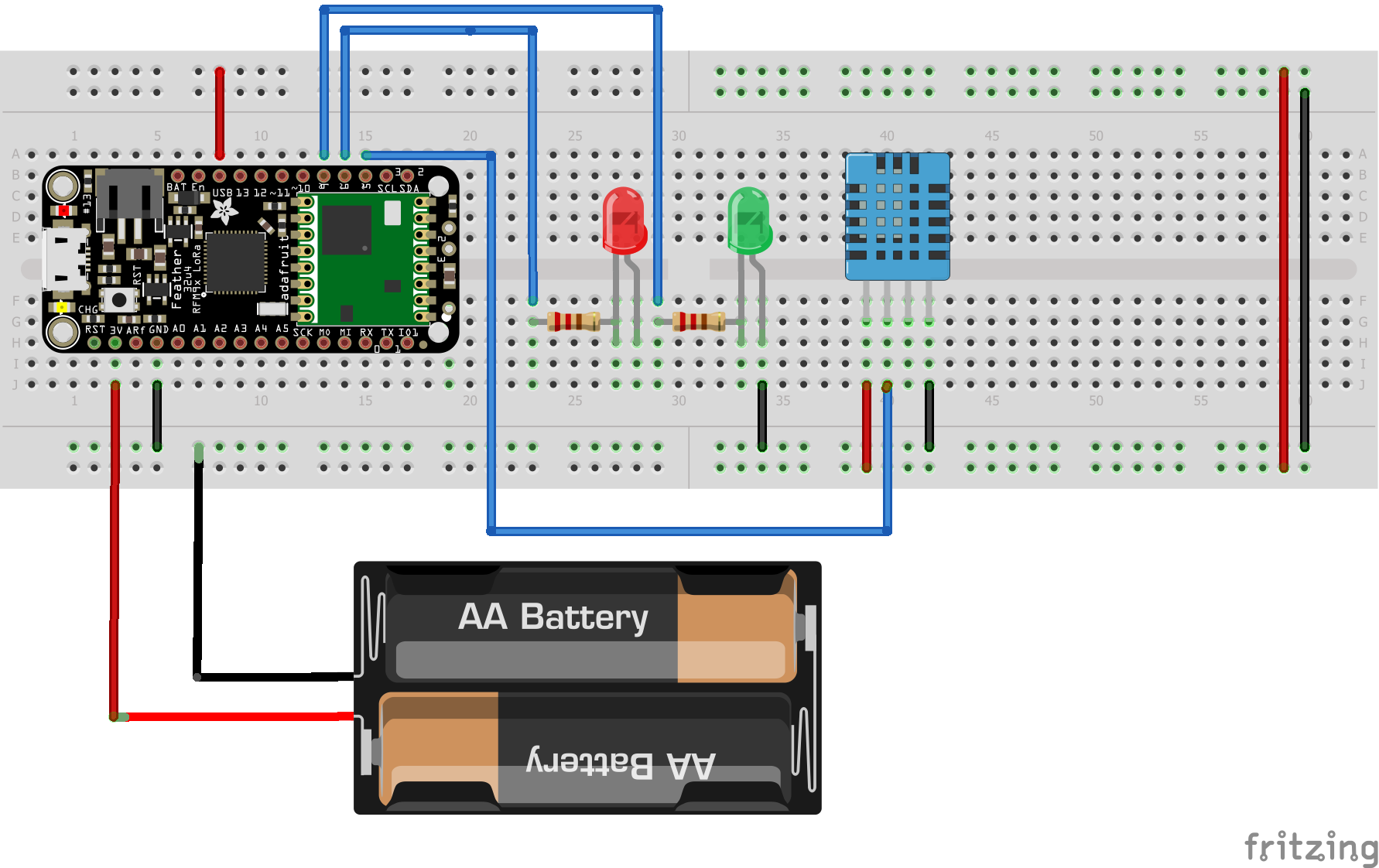
Any 3.3V power supply can be used to power the Feather or it can be
powered via the onboard Micro USB port. The USB pin on the Feather
outputs the same voltage as your power supply to the DHT11 sensor. There are several ways to power the
board that are detailed here.
The biggest take away here is using an external powersupply to power
the Feather and using the ports to get that power to your sensor.
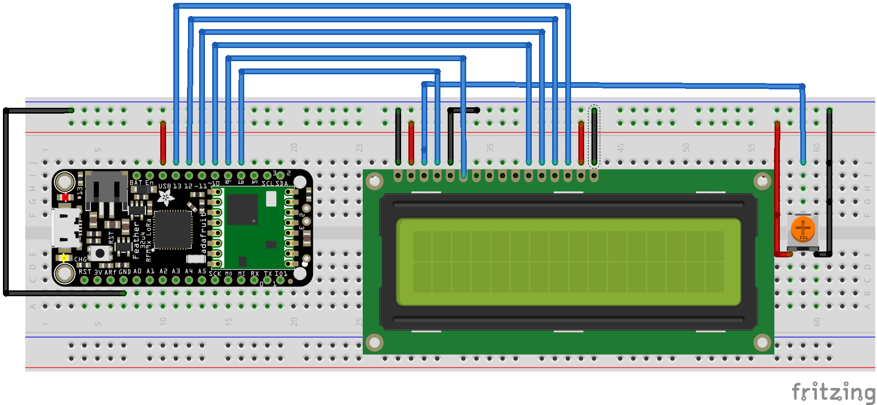
Reciever
The reciver is the central hub
that several transmitters send
to. It consists of a Liquid Crystal Display (LCD) that displays the
incoming data from our transmitters and a Serial Communication to a
computer to record the data.
Relay
The relay consists of the
Feather, 2 LEDs, a push button, and a
resistor.
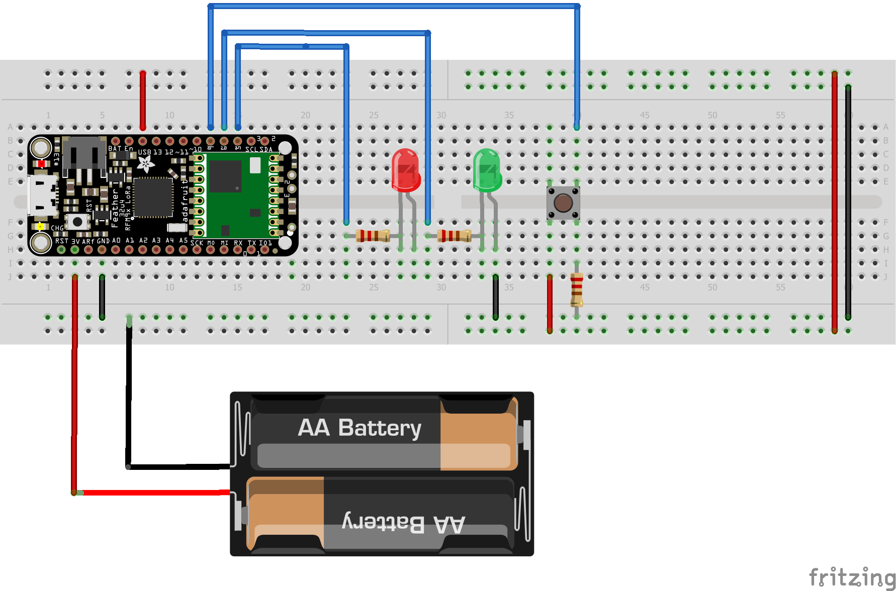
The idea behind the relay is that it will recive data from the previous
stage and transmitt it along. To change the identifier number of the
relay you hold down the button until the green LED blinks the same
number as the ID.
Software
Transmitter
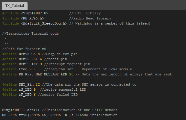
Now that we have the Feather setup physically it is time to tackle programming. Make sure you installed the libraries mentiond above, SimpleDHT, RadioHead, LiquidCrystal, and Adafruit_SleepDog. If not go back to IDE setup.
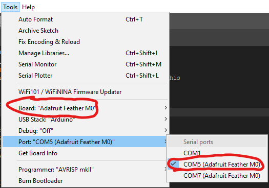
We will first start with setting up the transmitter. For this you will want to connect the Feather to your computer via USB. Now that it's connected there are two things that need to be checked. First make sure that under tools>Board>Adafruit Feathe M0 is selected. Second, that under Tools>Port: COMx (Adafruit Feather M0) is showing up. Your COM port number will vary. If you have trouble selecting the Board refer back to step 1) of setting up the IDE.
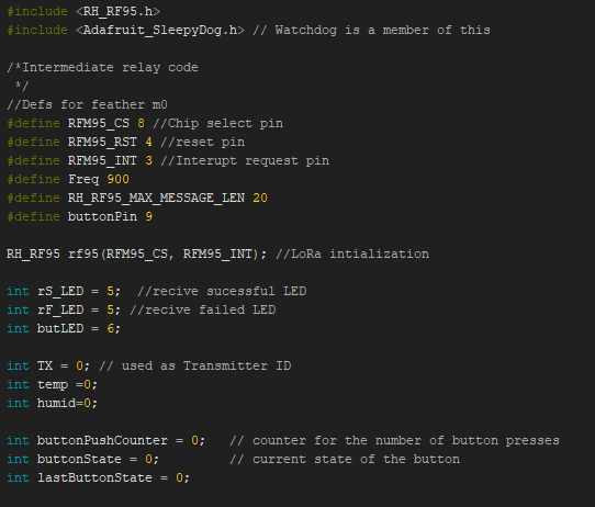
Above of the setup() and loop() functions we have the headers and a few variable definitions.
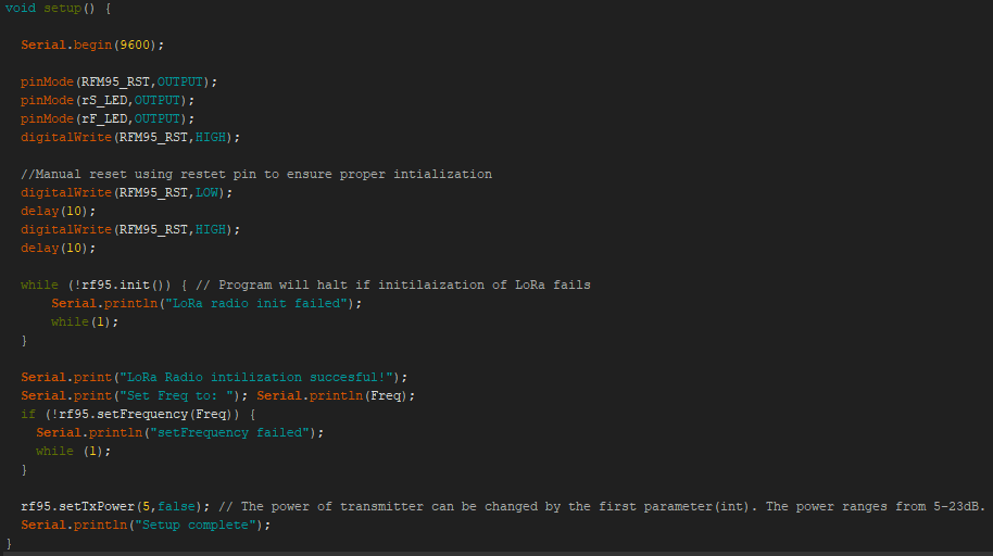
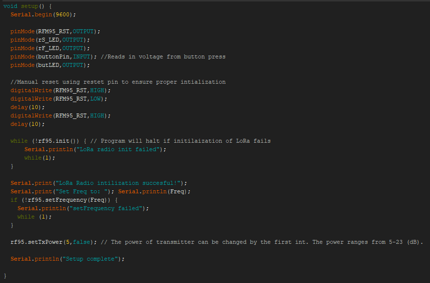
Next we will program the setup() function.
Lastly for the TX we will program the main loop().
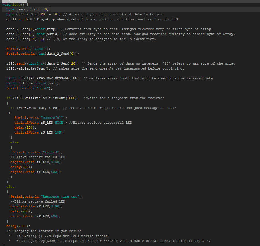
If you want to sleep the module you will need to uncomment the two sleep functions. The Watchdog.sleep() function will disable the serial communication with a computer, as a result the Feather will not be recognized via COM port. To fix this you will need to double press the built in reset pin on the Feather chip. The 13 LED will breathe red and you will be able to select a COM port for the Feather.
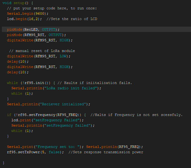
Reciever
We will next program the reciever that is capable of parsing data from several transmitters. Starting off with the seutp above the main loop.
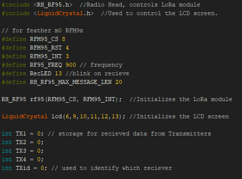
Moving on the the setup function.
Now we move on to the main loop that will gather the data from the several transmitters. We accomplish this by using a switch case that identifies which transmitter is sending and then updating the appropriate temperature.
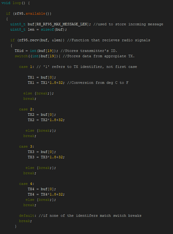
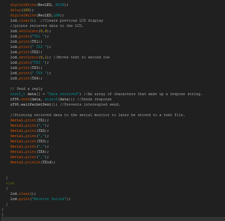
Now that we have the incoming data stored in our variables we can do things with it.
Data Collection From Reciever
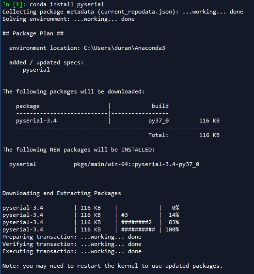
To record the reciever data from the serial monitor we will be using a Python script. The environment I used wasy Spyder. The library that enables serial communication with the Arduino is pyserial. To install this librarys you can type "conda install pyserial" in the console window. The library will then be installed.
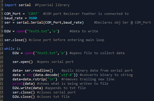
The data is encoded using utf-8
format, we decode it in line 19 to get it in the format of the serial
monitor. This script will run indefinately with this format. By
changing the while loop the duration can be controlled based on the
parameter you desire.
An alternative use of the Feathers is using them as relay stations allowing for more remote data collection. The general idea is that one Feather gathers the desired data and sends it to another Feather who's purpose is to relay it to the reciever. Along the way, each station could add its data to the packet heading to the reciever. The relay pulls from the TX and RX we made before, incorperating bits of each.
We will start off with the code above the setup and loop
Next we will move on to the setup function.
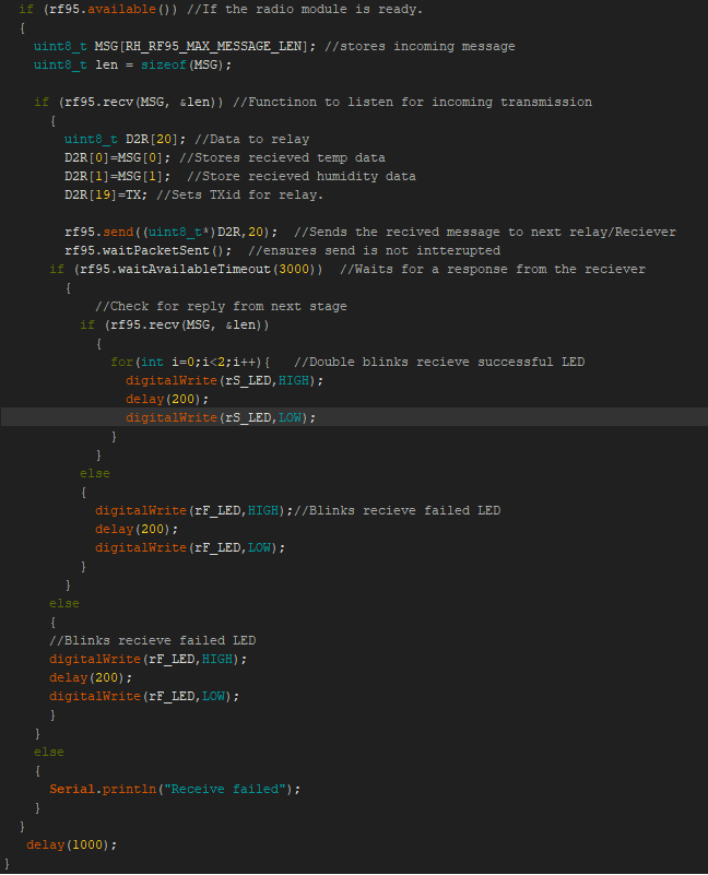
Now on to the main loop that runs. It has two actions that it preforms. The first is using the push button to set the relay ID# if the button is held down the LED will blink to indicate and increment the ID# of that relay. This allows for setting up several realys with the same code.
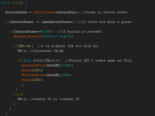
Second funcition is listening for the radio transmission from the previous stage and sending that data along.
Conclusions
Throughout this tutorial we explored several configurations of M0 Feathers w/ LoRa being used to transmit data. Going forward, adapt what you have learned here to the project of your choice. The world is your burrito, choose your own fillings.