2. Introduction
In this lab we will amplify a small signal (500 mVpp,1 Hz, 1 V DC
offset) to the 5-V range since is what or digital converter does.
3. Materials and Methods
LT Spice
Resistors
Function
Generator
Analog Digital Converter (ADC)
Breadboard
KompoZer
Multimeter
Wires
Capacitors
Oscilloscope
FileZilla
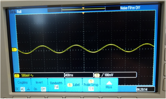
First, for task 1. A
signal was genereated using the function generator showed in Figure 1.
For task 2. We used the same signal and applied AC option in the
channel's menu to removed the DC offset for our signal(Figure 2). In
task 3. We
added a 3.3 V DC voltage from our 3.3V-5.5V module to the
sinewave we used before showned in task 1. and we showed DC and AC
coupling(Figure 3). For task 4. we added a low-pass filter to remove
the 60 Hz noise. with a given 3.4 Hz cutoff frequency and a 100k were
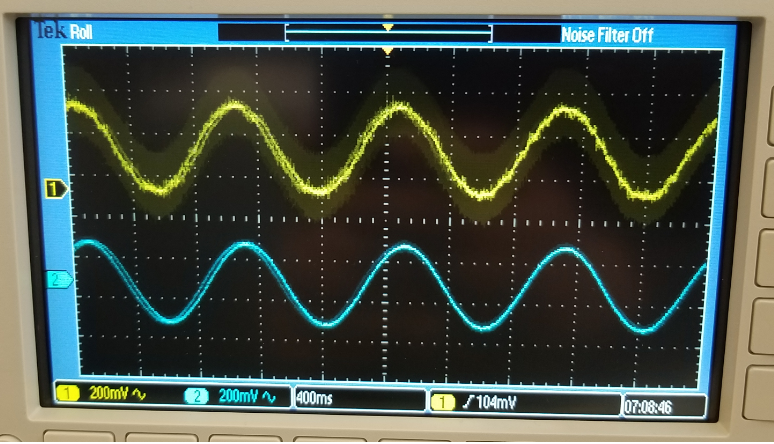
used (Figure 4). On task 5. we added a high pass filter to removed DC
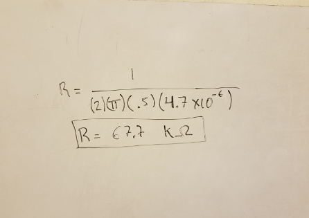
offset from signal(figure 5). we used 4.7 nF cap and calculate a
resistor that give us .5 Hz for cutoff frequency. In task 6. We added
some gain to the signal because it was being attenuated, so we used a
741 OpAmp, added a 2 V offset from a reference voltage, that we got
from a 680 ohm resistor and 1N4370 Zener diode Figure 6, we used and
schematic provided to assisted. Also we added a extra 10 V to get a
rail to rail voltage to prevent the lost of information and finally we
used an instrumental amplifier on DC coupling.
4. Results
Figure 1 Sinewave from the function generator DC coupling.
Figure 2 Sinewave with the offset removed using the AC coupling.
Figure 3 3.3 V noise added to the original sine wave.
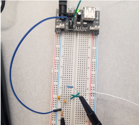
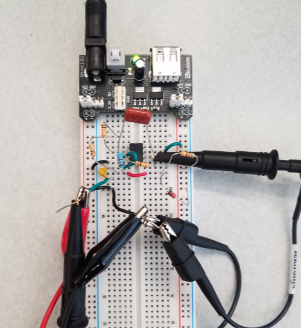
Figure 4. Calculations for R on the lowpass, circuit on breadboard and DC signal (noise) and the original sine wave.
Figure 5. Calculations for R for the high pass, circuit on breadboard and DC signal (noise) and the original sine wave.
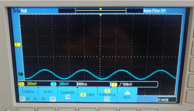
Figure 6 741 Op Amp with a high pass, a reference voltage and low pass. the signal its being cut on the bottom.
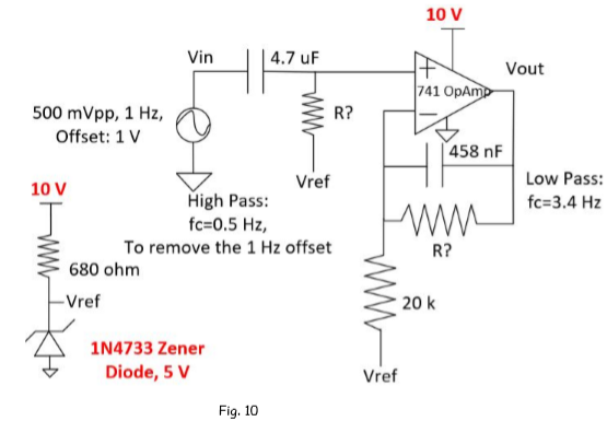
Figure 7. 741 Op Amp with a high pass, low pass, a reference voltage, increase the power of the amp to 10 V.
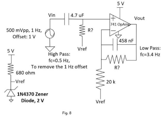
Figure 8 Circuit for task 3.1
Compensated probe for 10 DC Attenuation.
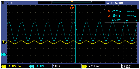
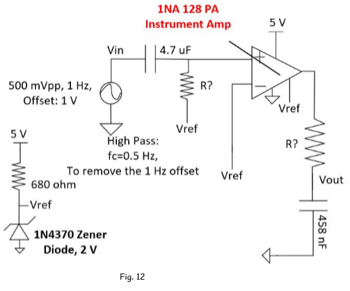
Figure 9 Instrumental amplifier used to simulated the previous task and compare.
5. Discussion
In this lab we focus on remove DC offset using DC coupling,
removing a noisy signal using high filters and low pass, and
incremanting the signal to avoid attenuation. We found out that we can
remove the DC offset using AC couppling, but that was not what we were
after, the point was to be able to do the same procedure for our own
seek to develop our own disigns. The calculations were done by having
in mind what type of cut off frequency we wanted, and values were
suggested by the proffessor. After using the Op Amp to clean the signal
and compering the results with the Instrumental amplifier, we found out
that the instrumental is better for this type of task. We can use a 741
amp but takes more effert to get our signal clean and amplified than
with a instrumental one.