ENGR201 Lab 2019 Lab
Lab 7
Name: Humberto
Arredondo Perez
Email:
harredondoperez@fortlewis.edu
1.
Operational Amplifiers
2. Introduction
In this lab students learned basic understanding of operational
amplifiers
(Figure
1).
By seting up differents circuits, students got some skills of the
function of op amps and learned how to amplified a signal given by a
function generator and were able to use the oscilloscope as well as the
power supply for testing.
3. Materials
-
Op Amp LM741
-
Funtion generator
-
Triple Channel DC Power Supply
-
Cables(for all connections)
-
Resistors
-
Potentiometer 100k and 1M
-
Oscilloscope
-
Generator
-
Multimeter
-
Breadboard
4. Methods
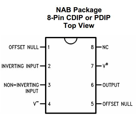
Figure 1. LM741 OP AMP
Task 1
Students Builded the following circuits (Fugure 2) on a breadboard and
filled up the table with the data was observed (Table 1).
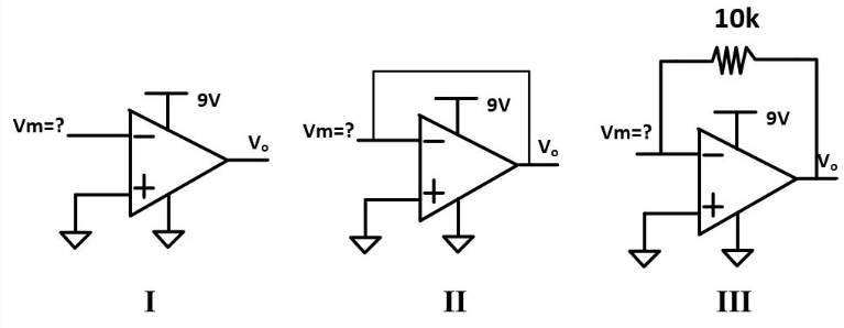
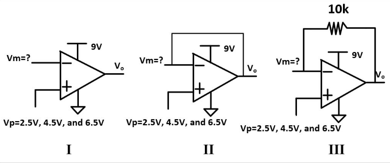
Figure
1 Differents circuits use to find Vout
Vp=0V
|
I
|
II
|
III
|
Vm
|
0
|
1.93
|
1.93
|
Vp=2.5V
|
I
|
II
|
III
|
Vm
|
0
|
2.5
|
2.5
|
Vp=4.5V
|
I
|
II
|
III
|
Vm
|
0
|
4.5
|
4.5
|
Vp=6.5V
|
I
|
II
|
III
|
Vm
|
0
|
6.5
|
6.5
|
Table
1 Results show Vp = Vm due to the negative feedback
Task 2
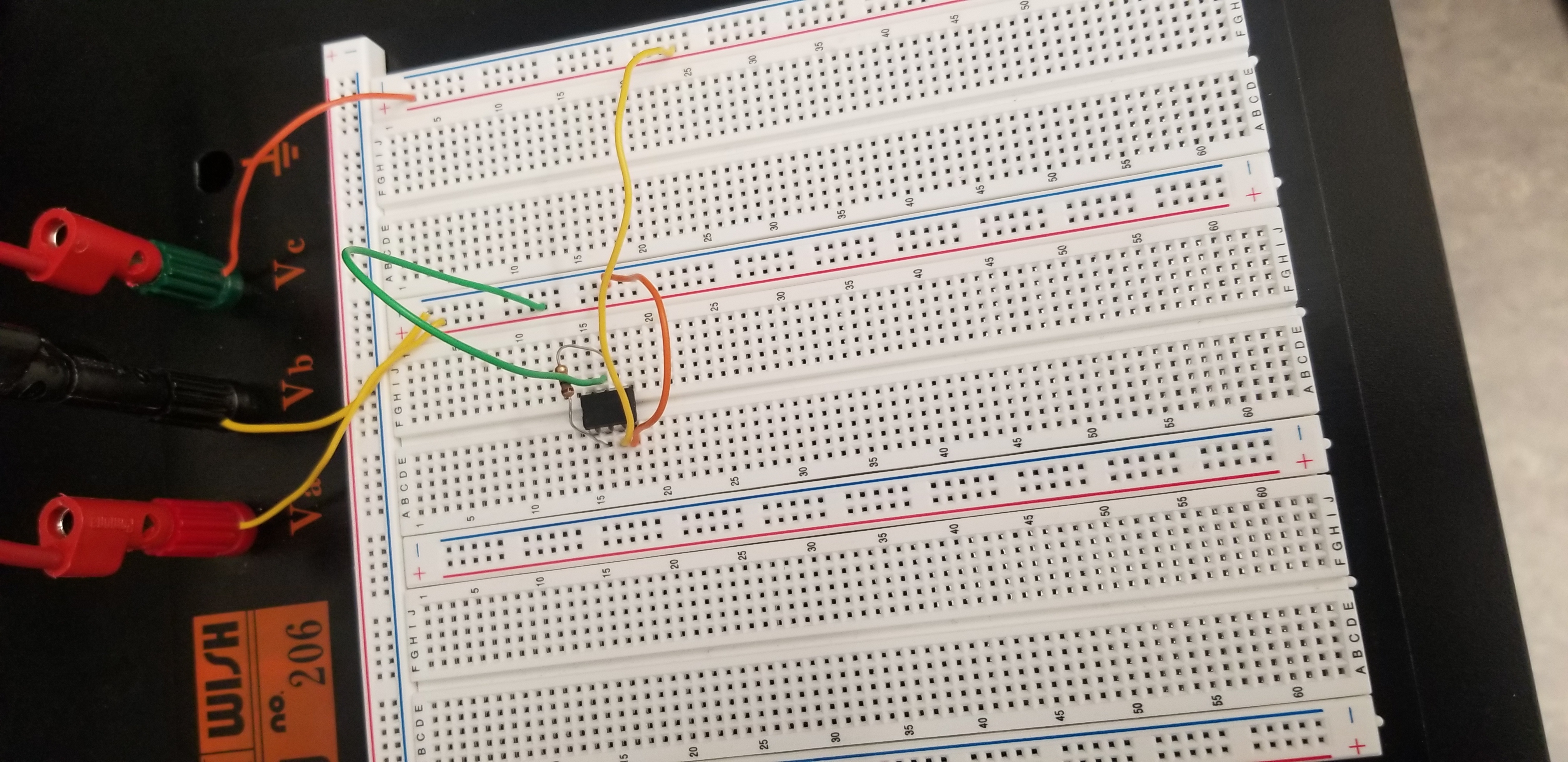
Maximum supply voltage and the input voltage that can be applied to the
Op Amp LM741
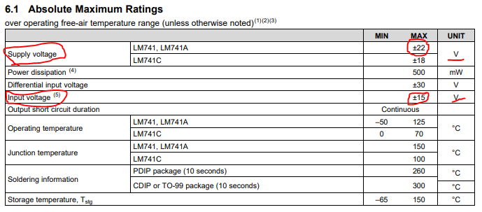
Figure 3. Max Supply and Input Voltage
Task 3
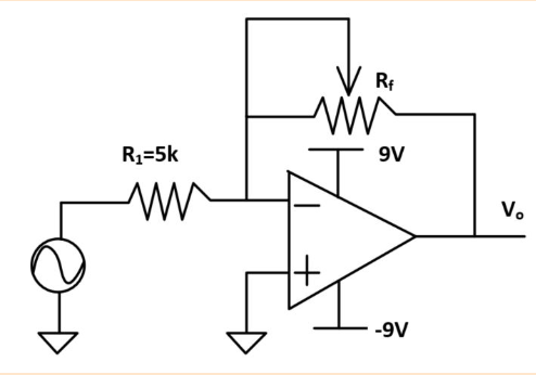
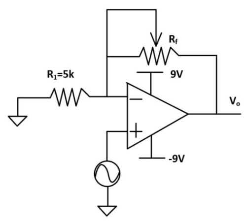
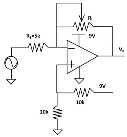
A R1=5k resistor and a potentiometer (100k) was connected to an Op Amp.
Powered up to OpAmp using +9V/-9V instead of 9V/GND. Connected the
input signal to a sine wave (1k Hz, 2V Vpp). Changed the resistance of
the potentiometer while looking at the scope (Table 4 and Table 5).
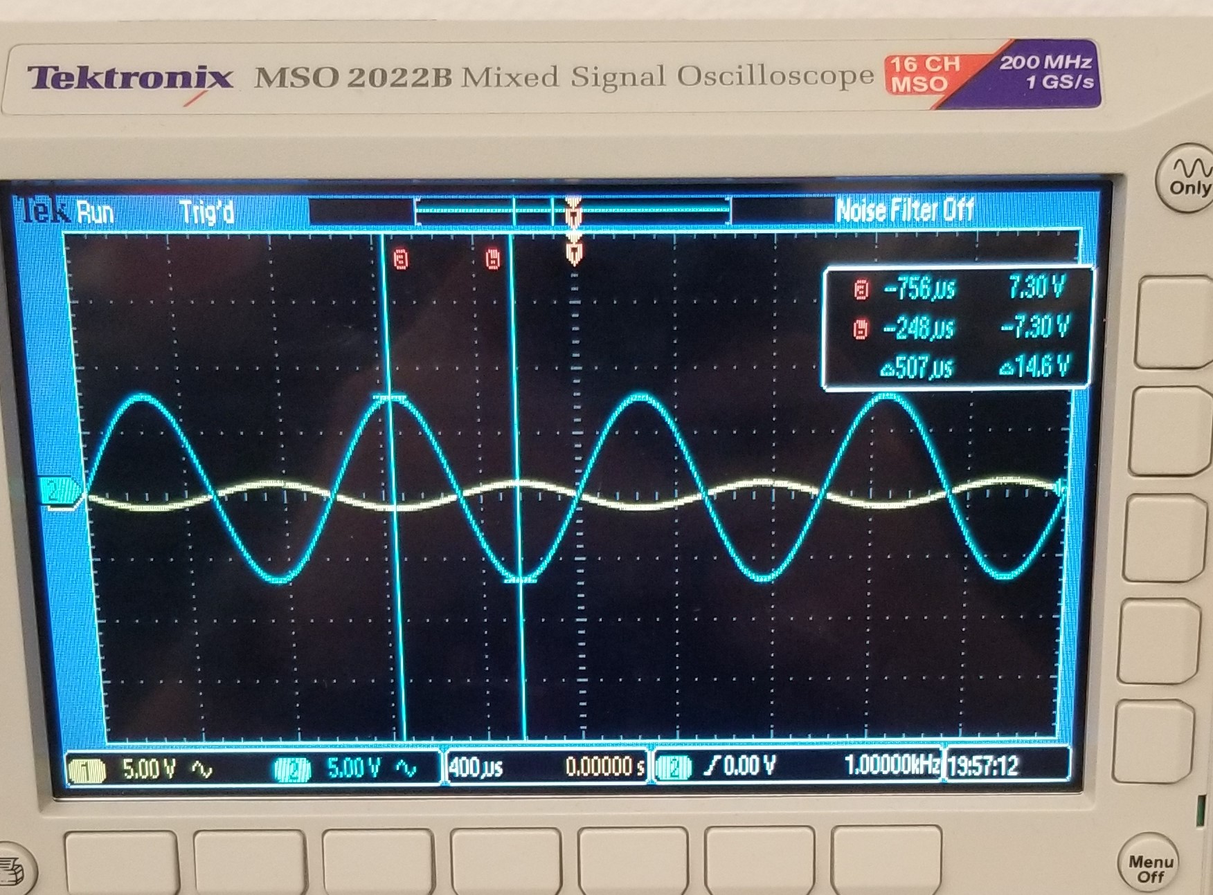
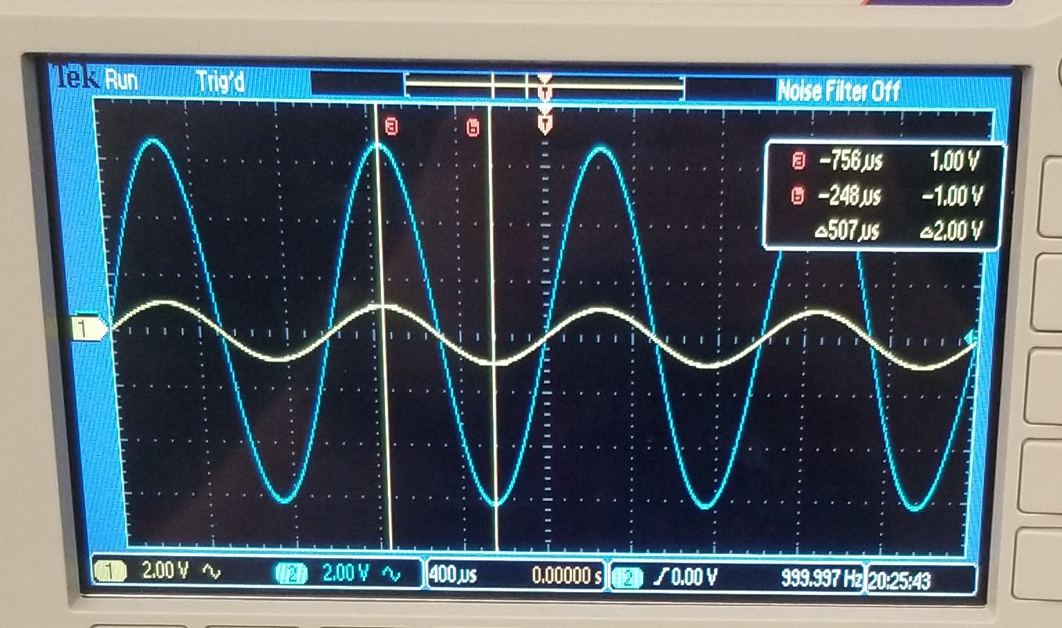
Table 4 circuits for task 3
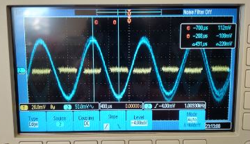
Table 5. Graph observed from the simulation of the circuitss from Table 4 (sine wave, 1 kH, 2V Vpp)
Task 4
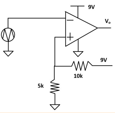
Change the -9V supply back to GND. Use a voltage divider to provide 4.5 DC 'bias voltage' to the non-inverting terminal.
Table 6 shows the task 4 from 0 to 9 v and a base of 4.5v
Task 5
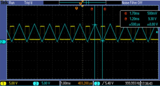
Inject a triagle wave (10V Vpp, 1 kHz) into the inverting terminal.
Table 7 shows task 5 triangle wave.
Discussion
In this lab students learned about operational amplifiers, how
toy behave, how to calculate the gain and experiment with inverting options.