| EAGLE |
Soldering Equipment |
Cables and Wires |
| PCB WAY |
4 AA Batteries |
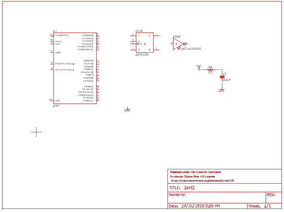
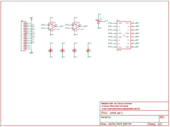
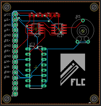
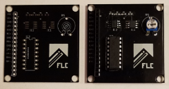
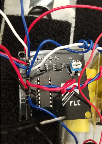
2 741 Op Amps |
| Power Supply |
PCB Board |
IR Emiters and Recievers |
| Multimeter |
2 Motors |
Potentiometer 10k |
| Robot Car Chassis |
Resistors 10k and 100 ohms |
L2934NA Chip 16 PIN |
|
|
 |
 |
 |
 |