ENGR201 Lab 2019 Fall
Lab 5, 10/10/19
Humberto Arredondo
harredondoperez@fortlewis.com
1.- Lab 5
The Robot Car Line Follower
2.- Introduction
In this lab the students learned how to design a driving circuit for DC
motors having a car go forward and followed a tape using IR sensors.
They were able to use sensors and electrical circuits to solve real
problems, they designed circuits using photoresitors, motor drivers,
and Op Amp comparators.
3.- The equipment and materials used
for this lab was:
Resistors with a different resistance capacity.
Wires
potentiometer
741 Comparator op-amp
Temperature-controlled soldering iron
Rosin core solder
A damp (not dry!) sponge to keep the tip of the soldering
iron clean.
Flux
Power source
AA batteries
Breadboard
DC motors
IR emitters and recievers
4.-
Methods and Results
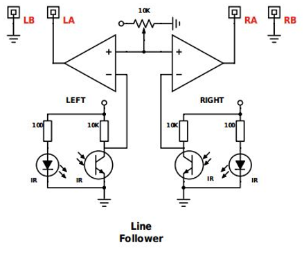
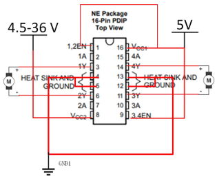
Schematics (Table 1) were used to make all the connections
of the components to a chassis with wheels. In order for our car to follow the
line, IR emitters were obtaining light from the clear surface of the table,
transforming that light in IR frequency that was send use to a IR receiver to
turn the motor on, when the emitter was over the tape (which it did not reflect
any light to the emitter) the motor will turn off, allowing for the other side
to catch up as showing on the video 1, and a final product is shown in Table 2
Table 1 Schematics used to built the car understanding how the
components work.
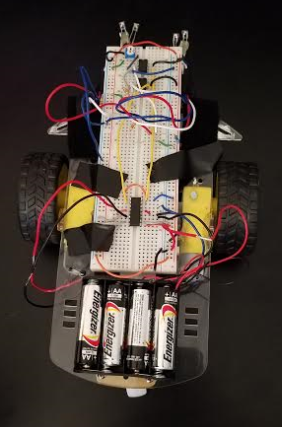
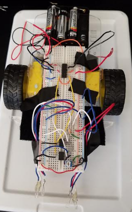
Table 2 Final product ready to race.
Video 1 The car performing along the clear color table following the
black tape.
5.- Discussion. Putting all the circuit together as we were learning what was happening
it was exiting, and to see how some theorical process was getting executing was
even better. The students found challenging to find the issues on the circuit
when it wasn't working but fixing was the reward part of it.