ENGR201 Lab 2019 Fall
Lab 4, 09/26/19
Humberto Arredondo
harredondoperez@fortlewis.com
1.- Soldering
2.- Introduction
In this lab the students learned how IR emitter and receivers work,
learned how to Build a light sensing circuit on a prototype PCB boardand the most important, they learned how to solder.
The equipment and materials used for this lab was:
Resistors with a different resistance capacity.
PCB board
Wires
LEDs
potentiometer 10k
Photoresistor or LDR 10k
741 Comparator op-amp
Temperature-controlled soldering iron
Rosin core solder
A damp (not dry!) sponge to keep the tip of the soldering
iron clean.
Flux
Power source
3.-
Methods and Results
Task 1.1
The Reading instructions and prepare for soldering was view by
the students and the teacher at the beginning of this lab.
Task 2
The circuit on Fig 1 was built on Prototype board, soldering the
components and testing them for errors to assure that it works (using the
bread board). The light sensor circuit can detect the intensity of
light. On this task it was configured to be on when there was light and
turn off when the light was blocked from it. An image of this circuit
can be seen on Table 1 and the circuit working on the video 1.
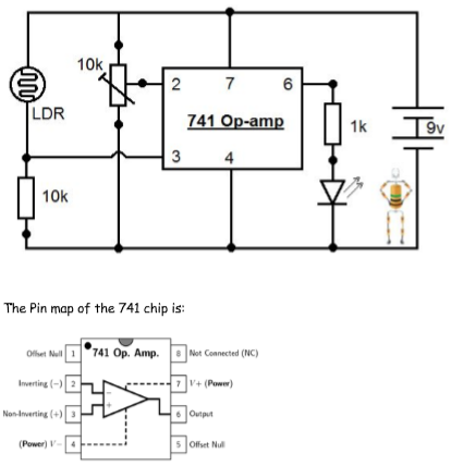
Fig 1. Light sensor circuit to be duplicate in this lab.
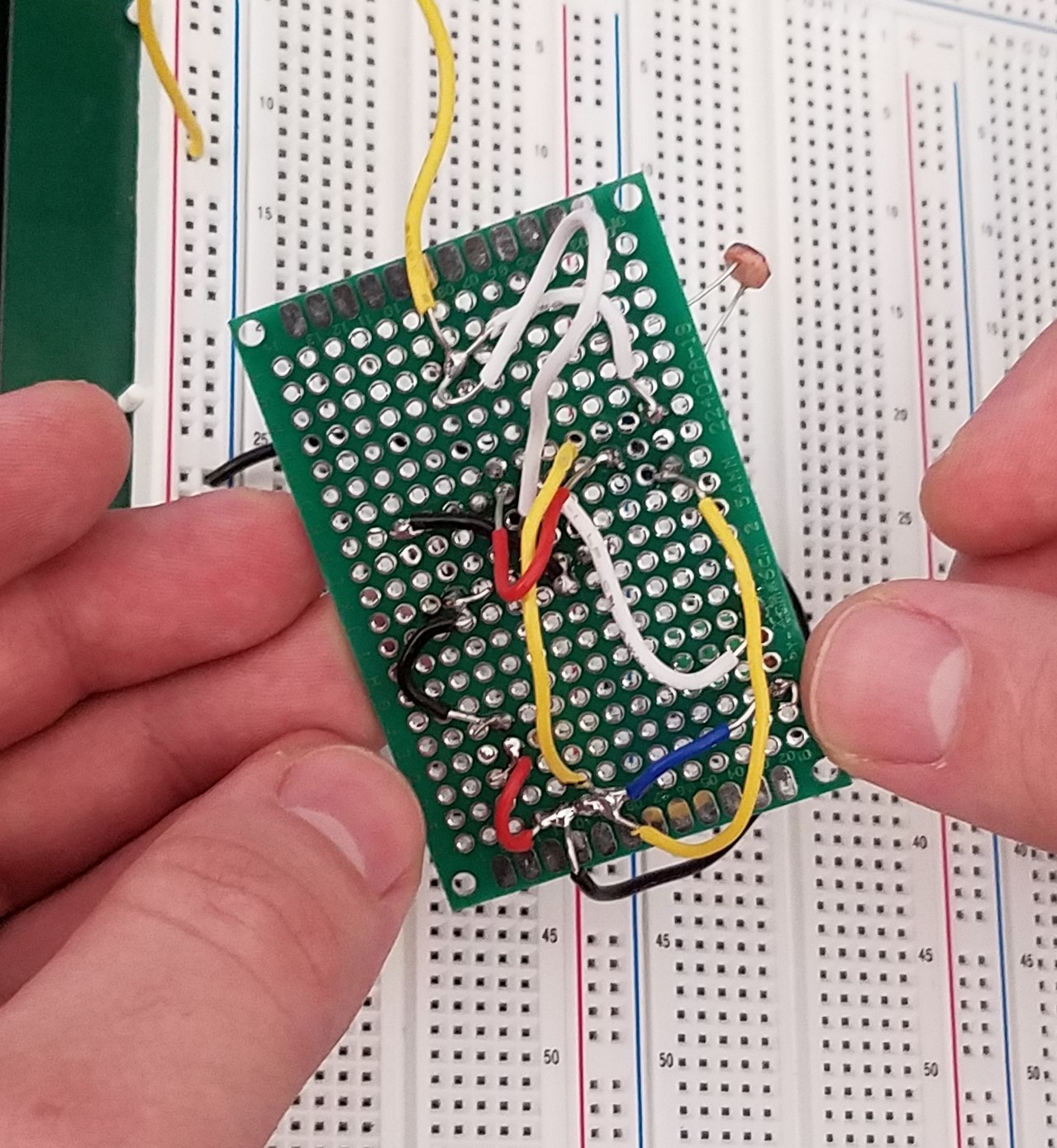
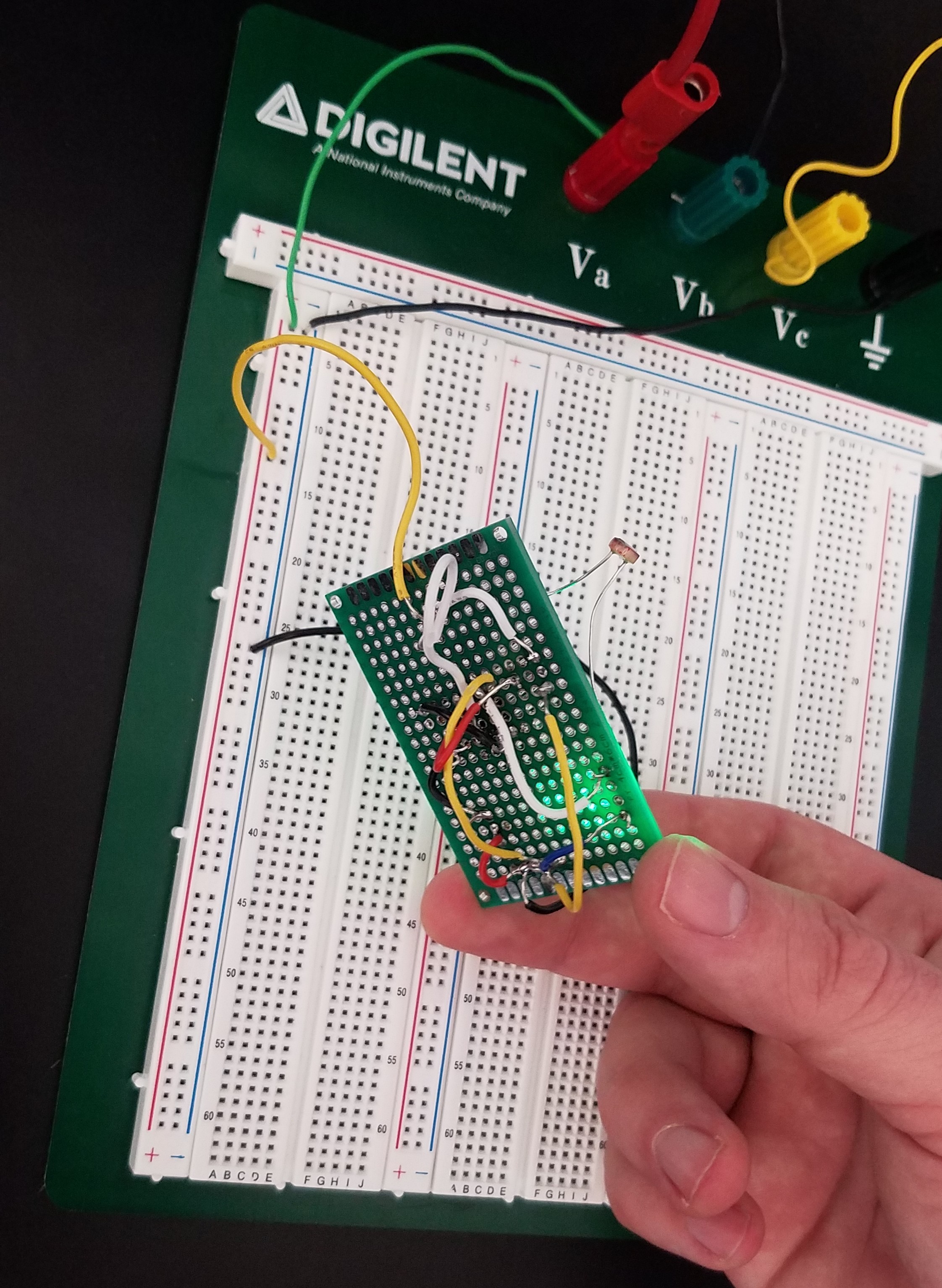
Table 1. Sensor Light circuit after
was complete and test it using a bread board.
Video 1. Sensor light circuit been tested.
Task 3
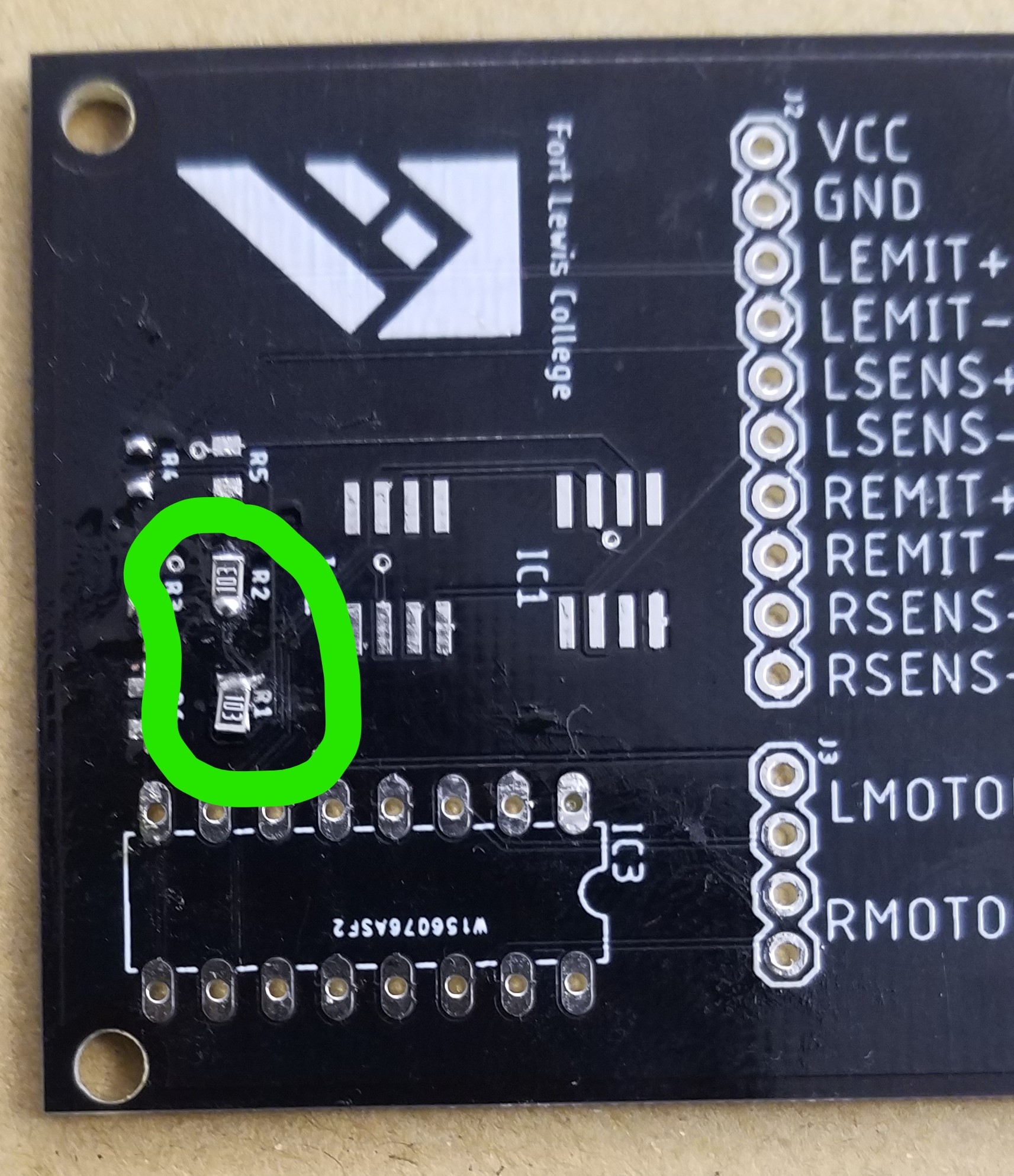
On this task a 10k resistor was soldered to a PCB as shown in Fig 2
Fig 2. PCB board with 2 resistors soldered inside the green circle.
4.- Discussion.
In the lab students learned the basics of how to solder. They put their
soldering skills to the test right away by building sensor light
circuit and see the beginning of how to build a PCB card that will be an
excellent tool in the future.