ENGR201 Lab 2019 Fall
Lab 3, 09/19/19
Humberto Arredondo
harredondoperez@fortlewis.com
Lab
3 Pushbuttons, LEDs, and DC Motors
1.- Introduction
In this lab the students learned how to use pushbuttons as switches to
control a circuit, how to use LEDs in a circuit, how to turn on and off
a DC motor using the bench-top DC power supply and using a motor
driver, and to use a photoresistor to control the speed of motors.
The equipment and materials used for this lab was:
Power Supply
Multimeter
Breadboard
Resistors with a different resistance capacity.
Wires
Pushbuttons
LEDs
DC Motor
L293D Pin
Photoresistor
2.-
Methods and Results
Task 1.1
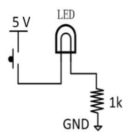
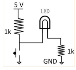
The circuit on Fig 1 was made on a breadboard to prove that the LED
light turned on when the pushbutton was pushed (see Fig 2).
Fig 1. Circuit shows a LED light connected to a push button and a
resistor.
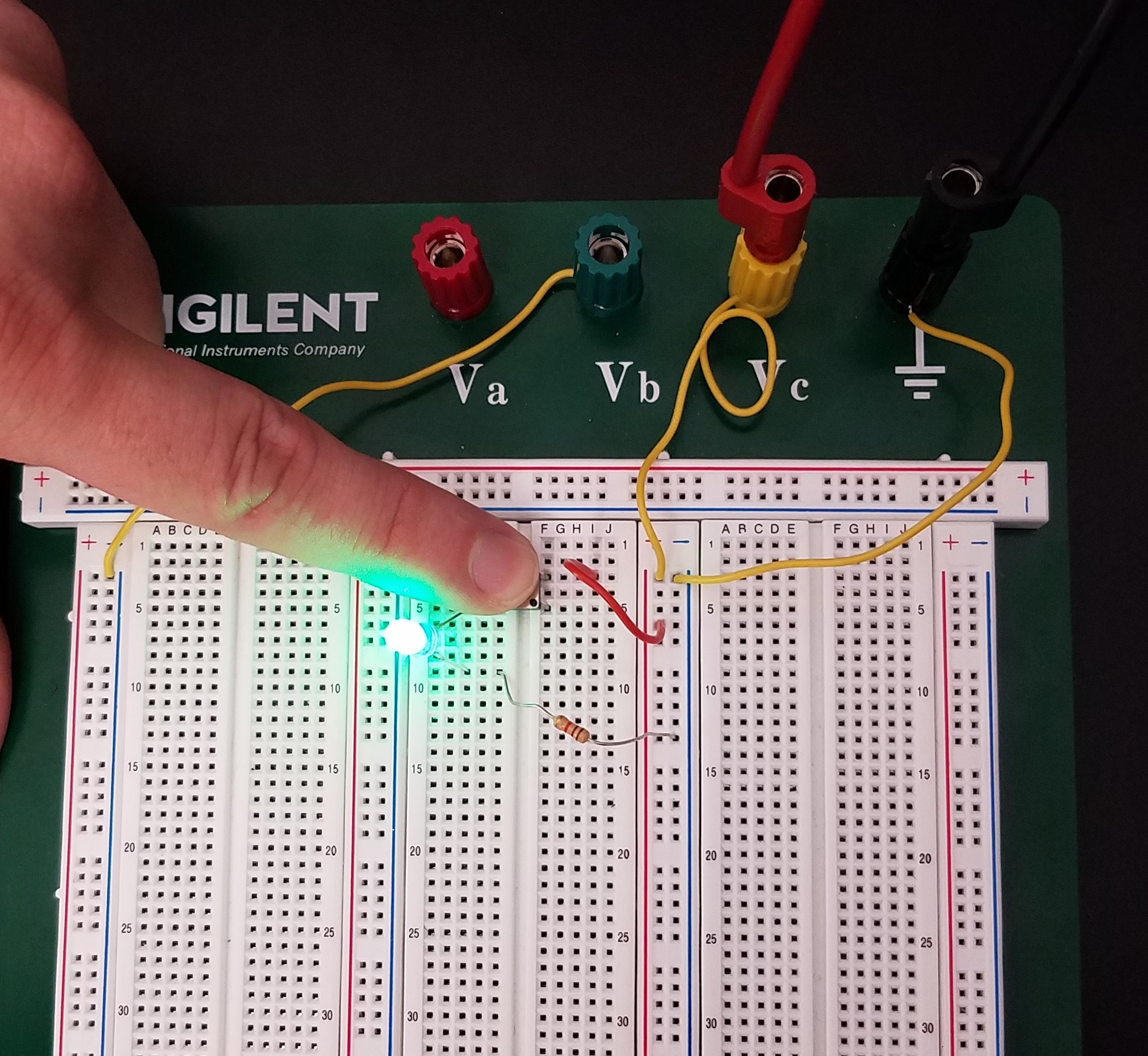
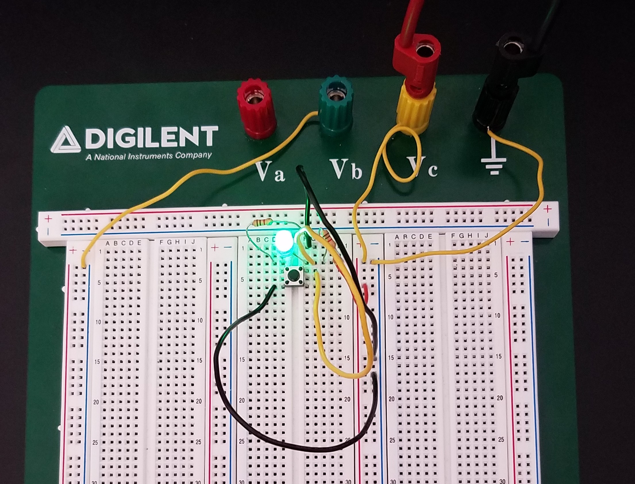
Fig 2. The circuit on Fig 1 on a breadboard showing the LED light on
while pushing the pushbutton due to closing the circuit and allowing to
have a current.
Task 1.2
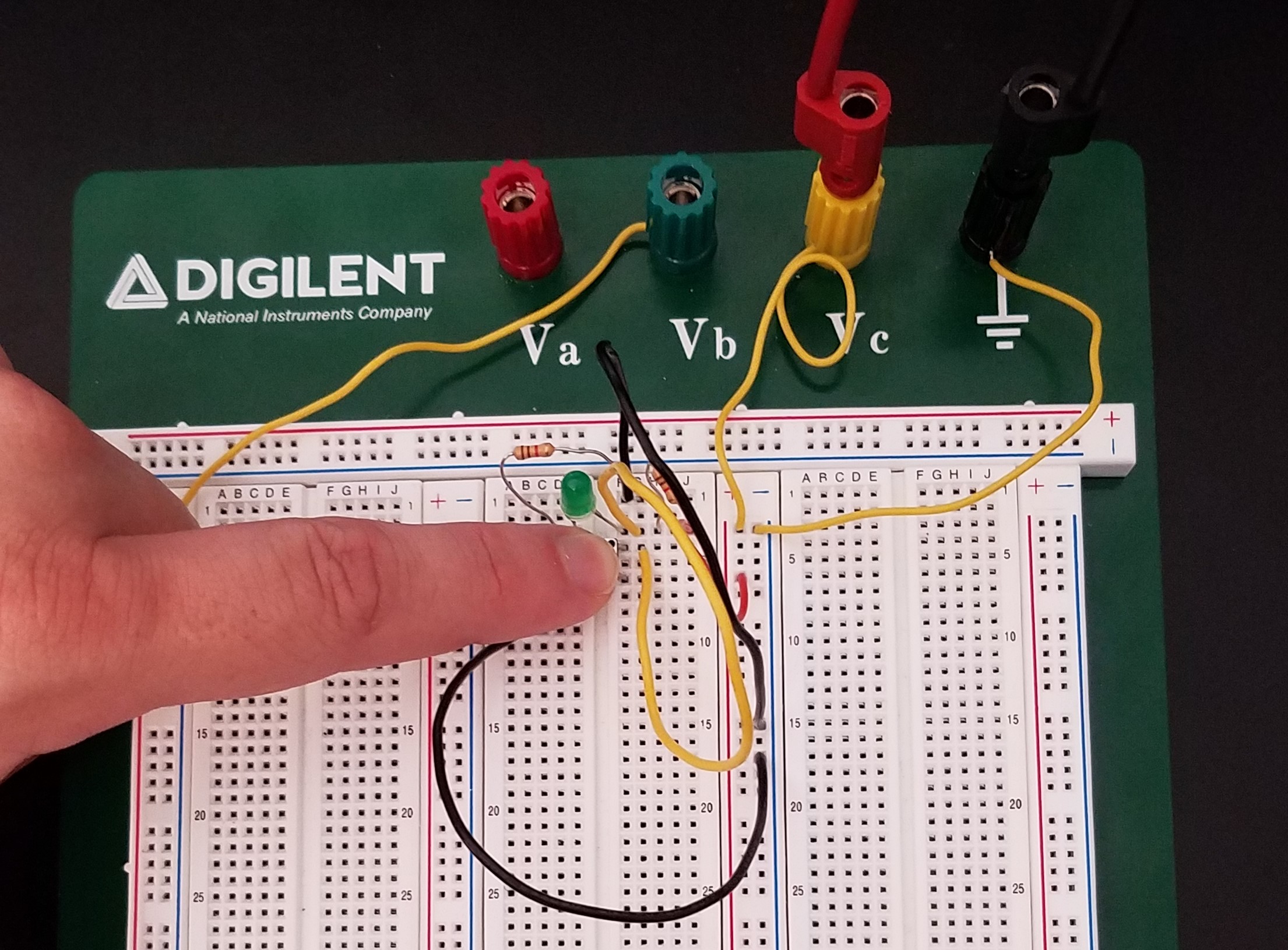
The circuit on Fig 3 was used to turned the LED light off when the
pushbutton was pushed (see Fig 4 and 5).
Fig 3. A LED light connected to two resistors but being grounded before
the anode by the pushbutton.
Fig 4 The circuit on Fig 3 made on the breadboard.
Fig 5. The circuit shows how the LED light goes off while the
pushbutton was pushed due to the circuit being grounded right before
the anode, causing a total dropped of voltage before the LED.
Task 2
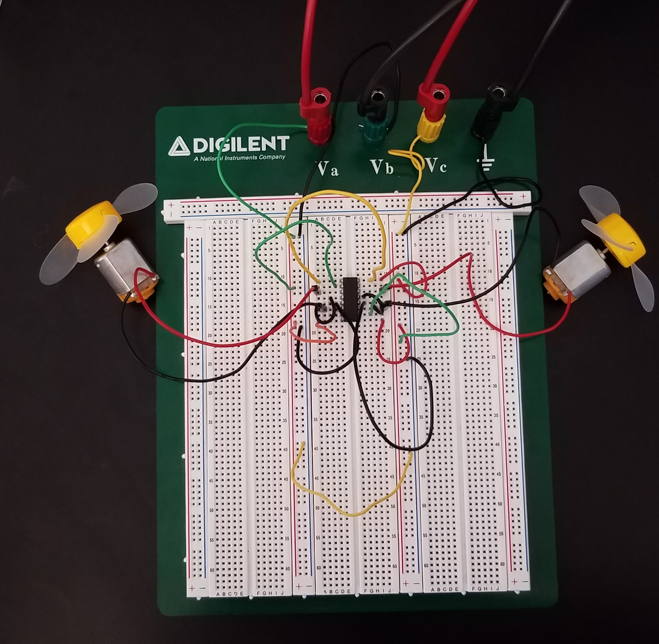
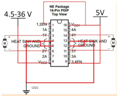
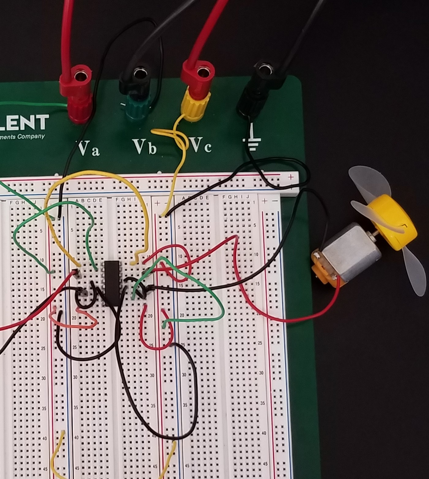
On the breadboard the L293D was wire to make a motor spin using the
structure of Fig 6 and increased the voltage input to make the motor
spin faster (see Fig 7).
Fig 6 Sample on how to wire a L293D component to make a motor spin.
Fig 7 Circuit made on breadboard showing the sample on Fig 6, and
tested for different voltages and was observed that the speed increased
when voltage increased.
Task 2.1
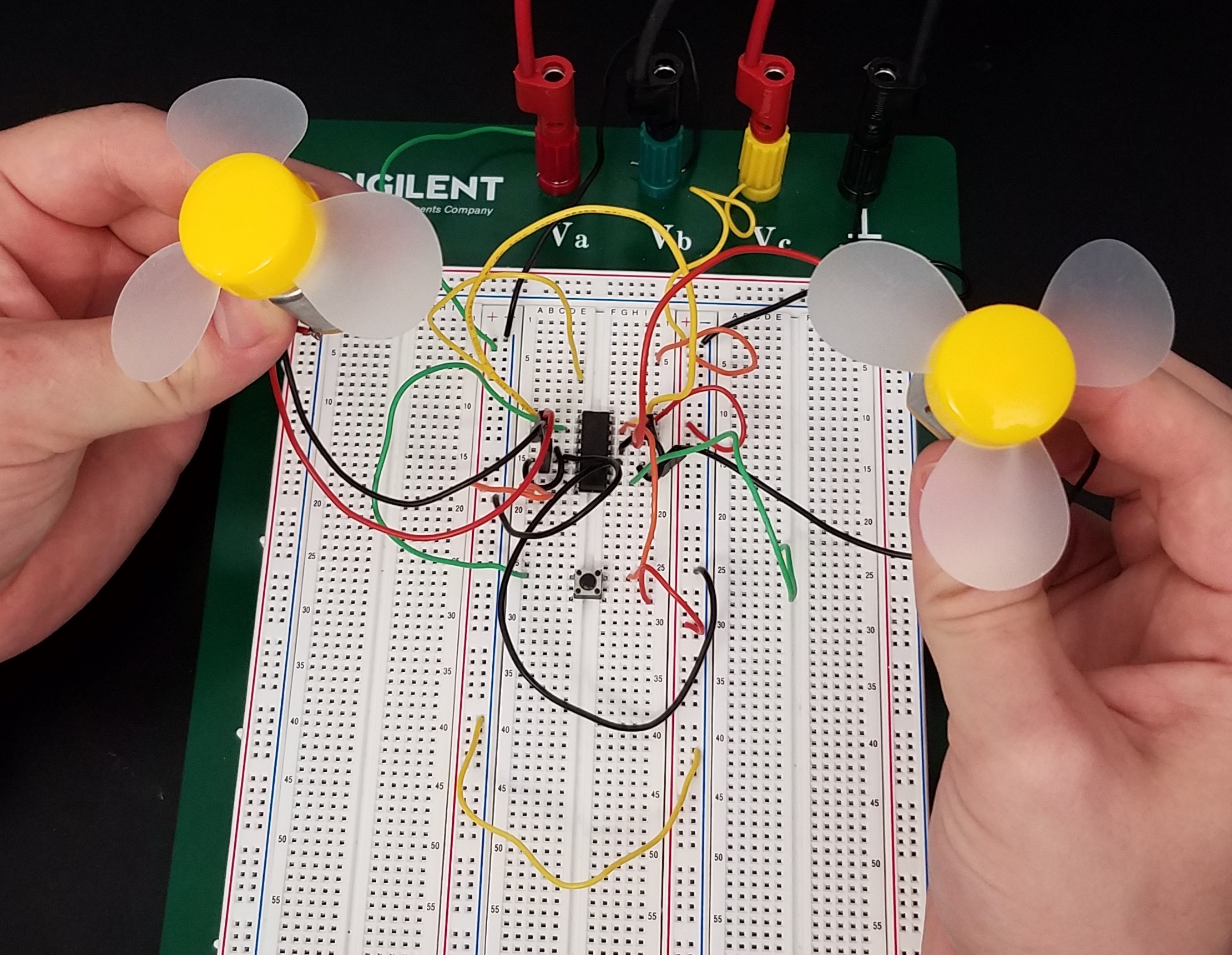
The circuit of Fig 6 on the breadboard was used to connect two DC
motors on Table 1.
Table 1. Circuit shows a L293D connected with to DC motors being power all time.
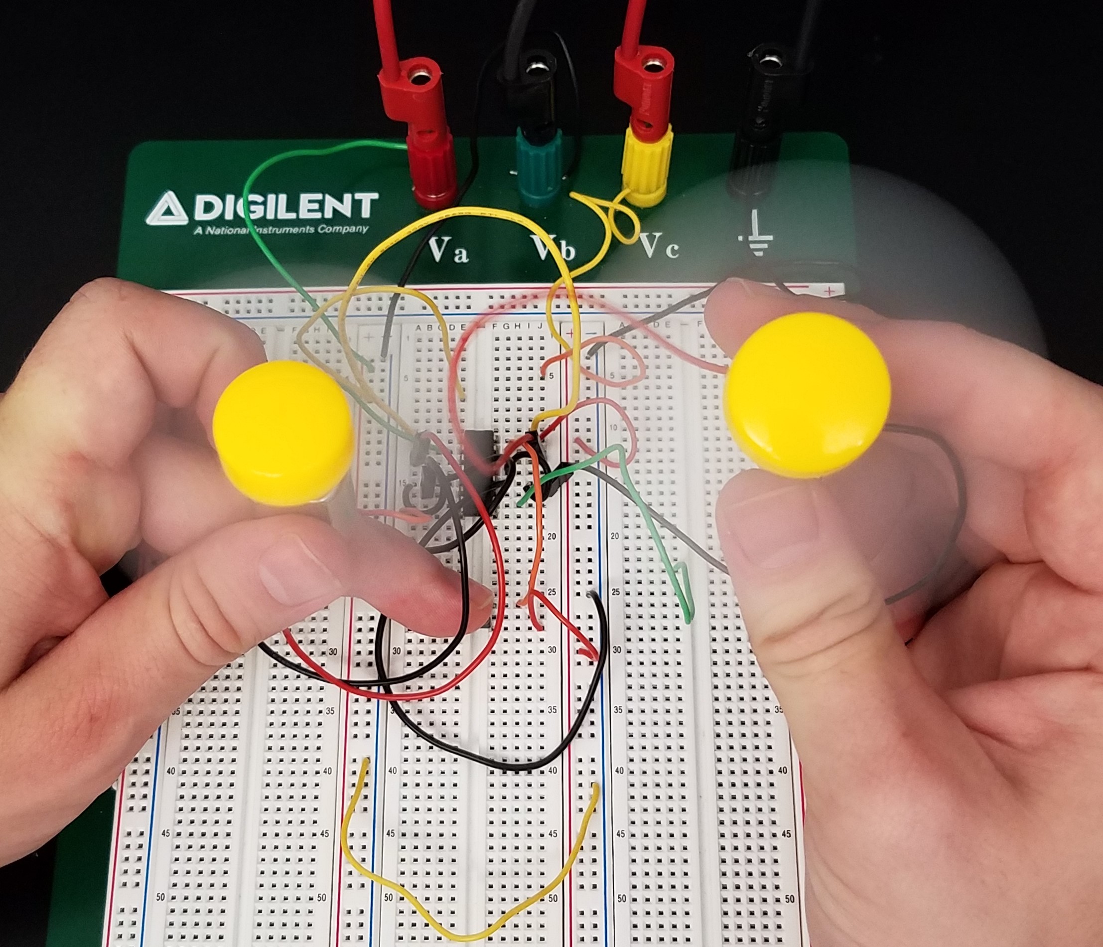
Task 2.2
Two pushbuttons were added the circuit to control the on/off option for the motors (Table 2).
Table 2. Circuit shows a L293D connected with to DC motors control by pushbuttons.
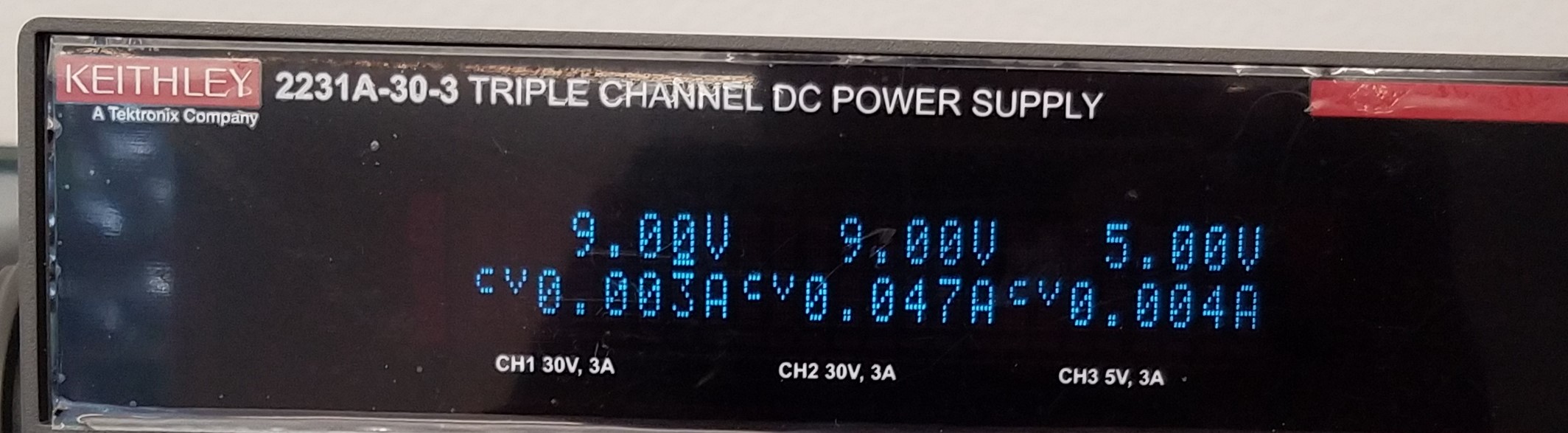
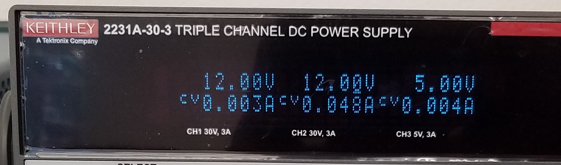
Task 2.3
The voltage was changed from 5v to 9v and 12 v(see Table 3)
Table 3. 9v and 12v are being apply to circuit.
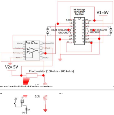
Task 3.1
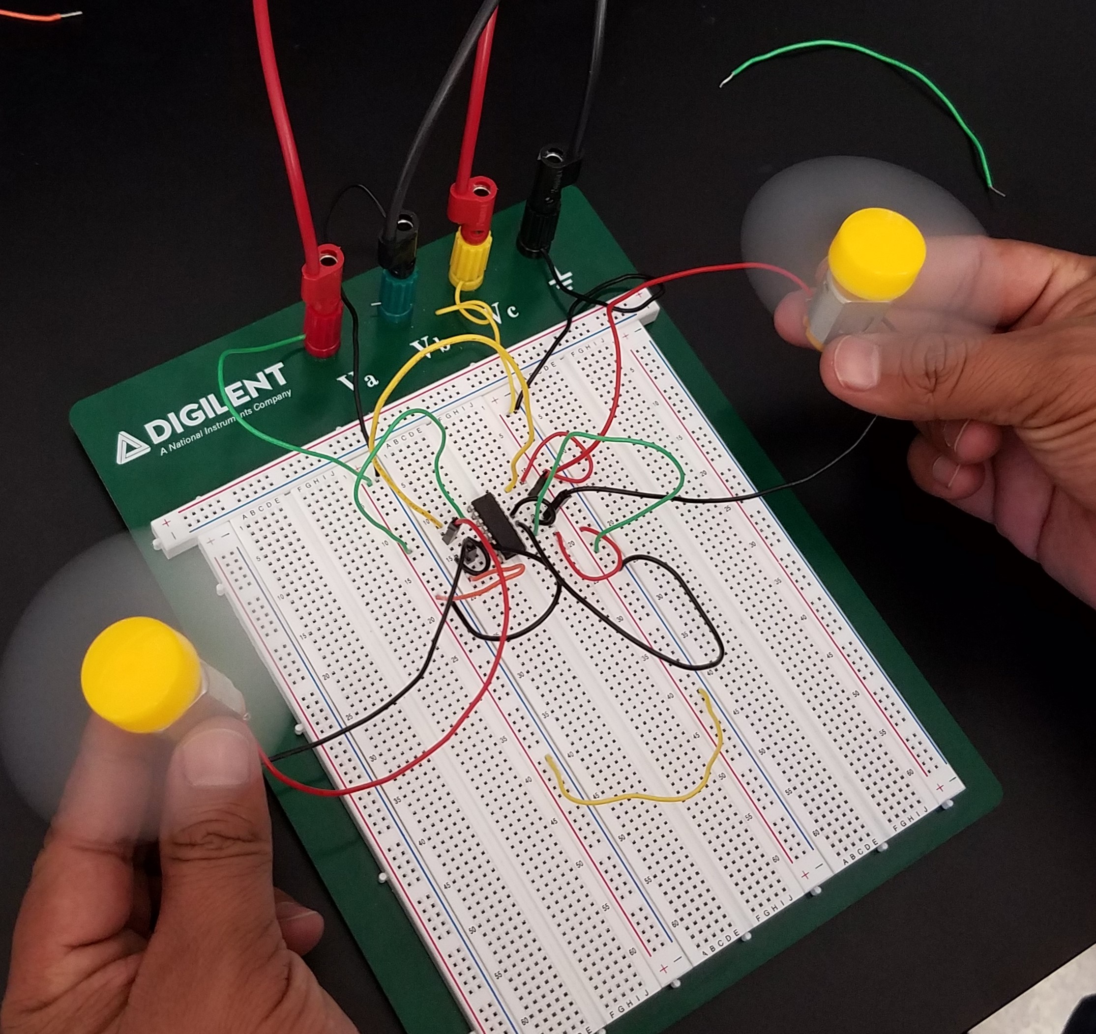
A 741 chip was used for this task (Fig 8). The output voltage of the
voltage divider was being connected to the input of the amplifier (gain
= 1), the output was connected to '1A' and '4A' to turn on/off the
motors. So, the output of the voltage divider was isolated from the low
input resistance of the driver. The circuit was made in breadboard, but
this time a photoresistor was use as a speedometer for the motors, and
this one was being trigger by light from a LED that was turn on and off
by a pushbutton (see Video 1).
Fig 7 Circuit from Fig 6 and additions such as a photoresistor, another pushbutton and a LED light.
Video 1 Shows a circuit with a pushbutto that turns a LED light on, and
this one gives light to a photoresistor that turns two motors on.
Discussion
In this lab the students were able to use a photoresistor as a sensor
and pushbuttons as switches to turn LED lights and two electric
motors on/off on a circuit.