Robotics is a fun way to delve into DC
circuitry and digital logic. For this project, you will use the
information
learned in previous weeks to assemble a car that follows a line.
The car can follow the line by using infrared (IR) sensors to move with
the absence
or presence of infrared light. The sensors used in this tutorial have
been
modularized for you.
These modules consist of an IR transmitting light emitting diode (LED)
that emits only infrared light,
an IR
phototransistor, a potentiometer, a dual differential comparator
chip,
and two regular LEDs; one to indicate power, and another to indicate a
change is detected.
The IR phototransistor is a diode with a special
coating that only lets infrared light pass through. It acts as a
resistor that is affected by the amount of light that
contacts
it's surface;
with a resistance of around 1k ohms when light is detected, and around
1 million ohms when no light is detected.
A potentiometer is a type of resistor that has a
resistance value
that can dimmed or enhanced by turning a knob. It's being used in this
circuit as an open amplifier, or "op-amp," for an open loop gain.
The open loop gain being so high is what keeps the output voltage of
the comparator at an extreme; converting the output to discrete,
digital outcomes of low, 0V, and high, maximum voltage.
The dual differential comparator chip is being
used to convert the
signal of the IR phototransistor from an analog signal to a digital
signal by comparing the reference voltage, from the voltage dividing
op-amp,
to the voltage being sent from the phototransistor, and amplifying the
difference to the closest extreme value.
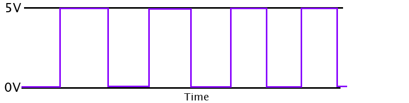
Digital signals have discrete potential values
that are used to
represent Boolean
bits. When
the potential is low, at 0 volts, it sends a 0, and when the potential
is high, at the maximum available voltage,
it sends a 1. Because of this, the signal comes out as a
square wave on a timing chart. The diagram could look like this:
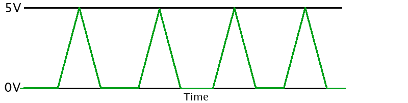
Analog signals are not discrete in potential, and
can look like
triangle waves when plotted over time; which could look like this:
The signal from the module is sent to a driver.
The driver uses digital logic to control the motors.
The
driver then executes the logic through the motors.
The logic the driver uses for the different steering movements are
shown in the figure below:
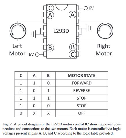
American Journal of Physics85, 333 (2017); doi:
10.1119/1.4979648
This figure is a snippet from a PDF that can be
found here. It has more details about this project.
| Bolts/Stand-offs |
Quantity |
| M3*30 |
4 |
| M3*10 |
2 |
| M3*6 |
8 |
| M3*5 |
2 |
| M3 nut pieces |
8 |
| M3 washer pieces |
4 |
| M3*6+6 Standoff |
4 |
| L12 Standoff |
4 |
| Component |
Quantity |
| Baseboard |
1 |
| Hammer Caster Wheel |
1 |
| Motor Fasteners |
4 |
| Encoder Discs |
2 |
| Wheels |
2 |
| Deceleration DC Motors |
2 |
| 3.7V Batteries |
2 |
| Battery Pack |
1 |
| Screwdriver |
| Small/Needle-nose Pliers |
| Wire Cutters/Strippers |
| Wire for Connections |
| Breadboard |
| Soldering Iron |
| Solder(60/40) |
| Type |
Quantity |
| IR Sensor Modules |
2 |
| DC-DC Converter |
1 |
| I2C L293D Driver |
1 |
| MC14049U Inverter |
1 |
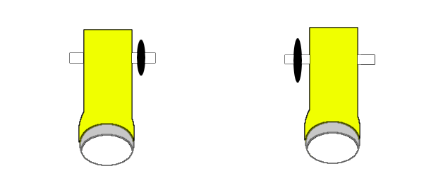
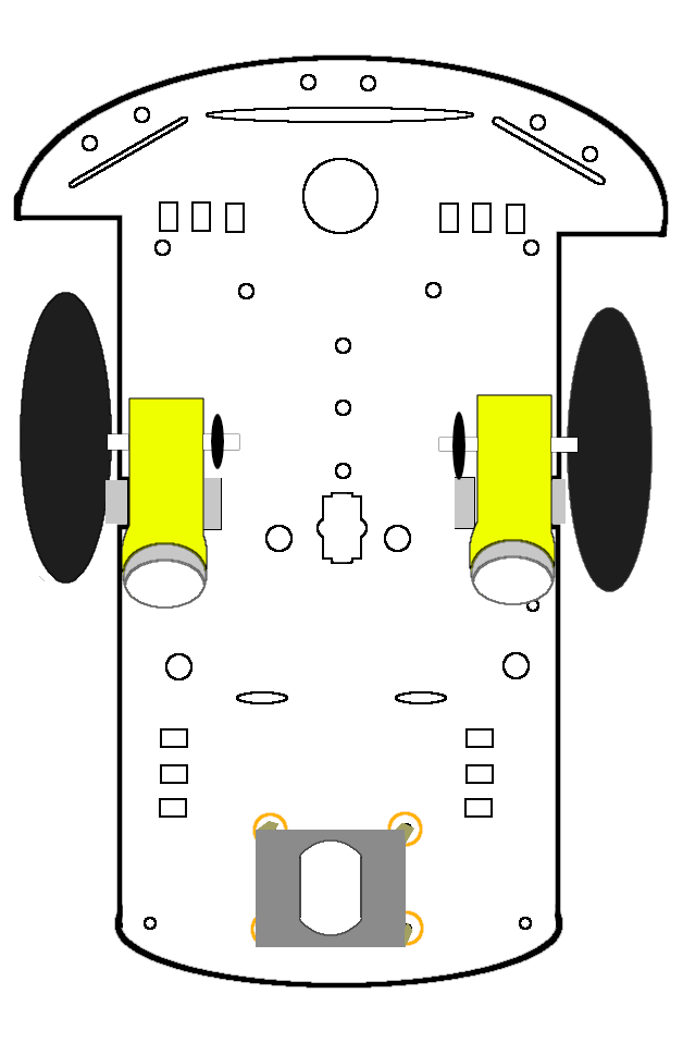
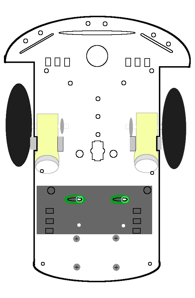
Attach an encoder disc to a protruding arm of each
deceleration DC motor. The motors look like they have a button on a
side. These
are not buttons, but you can use them to orient your motors on the
baseboard.
Have them
facing away from each other and put the encoder discs on the arms that
will be
facing each other as shown in the figure below.
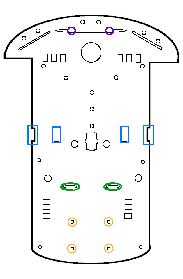
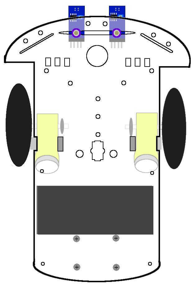
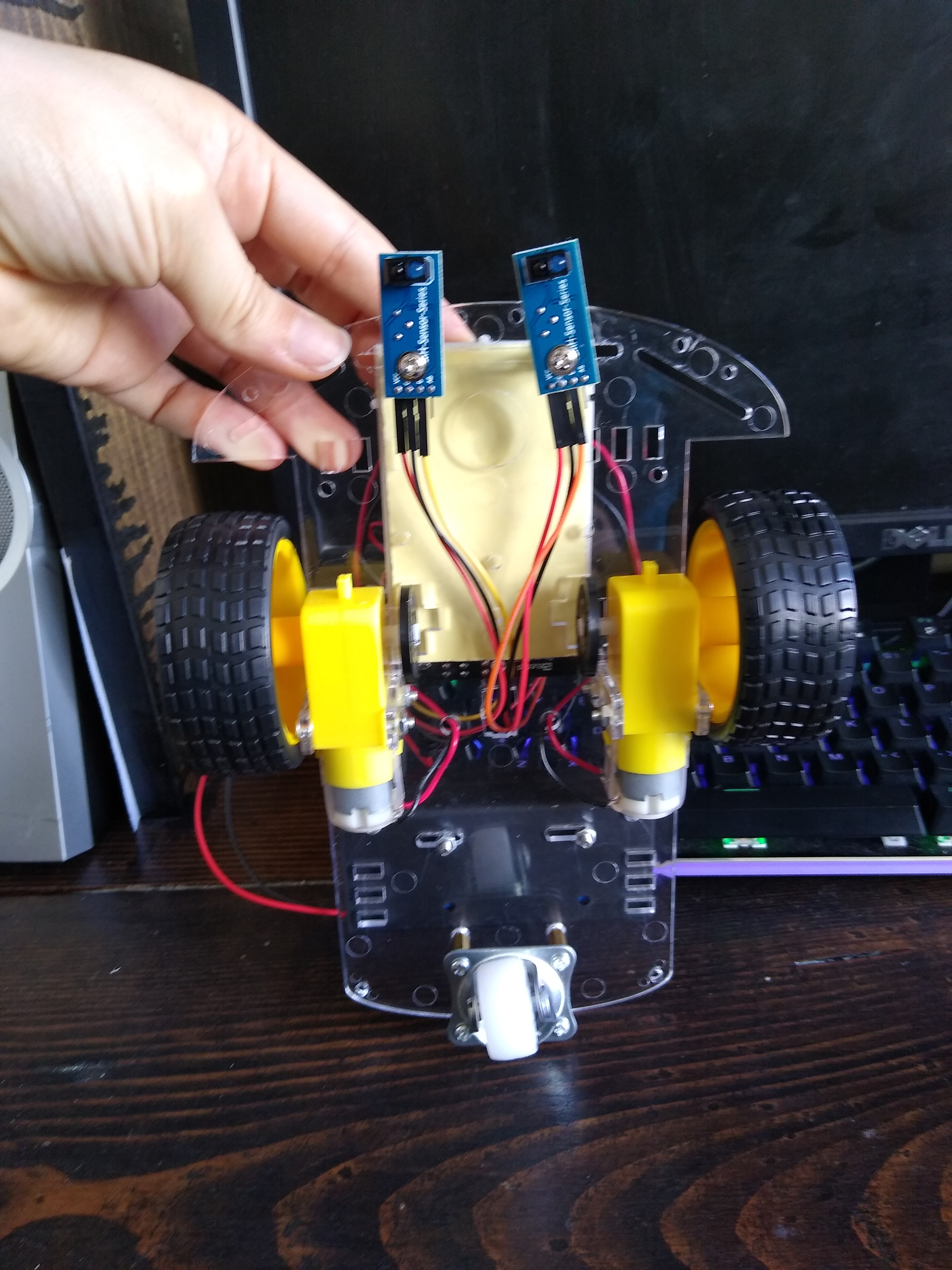
After the battery pack is secured, attach the IR
sensor
modules to the front of the car. To do this, we need to use the four
M3*6+6
standoffs, four M3 washers, two M3 nuts, and two M3*5 bolts.
Connect two standoffs to each other. This offsets the sensors closer to
the
ground while leaving room to access the potentiometer. This will help
when
troubleshooting and calibrating the sensors.
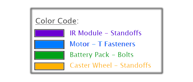
Install the standoff to the chassis by inserting the skinny end into
the long hole that is outlined with
purple, as shown, from underneath the frame. Add another washer to the
topside, and secure it with a nut.
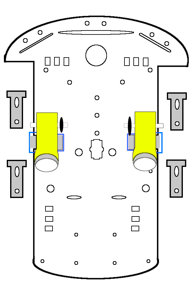
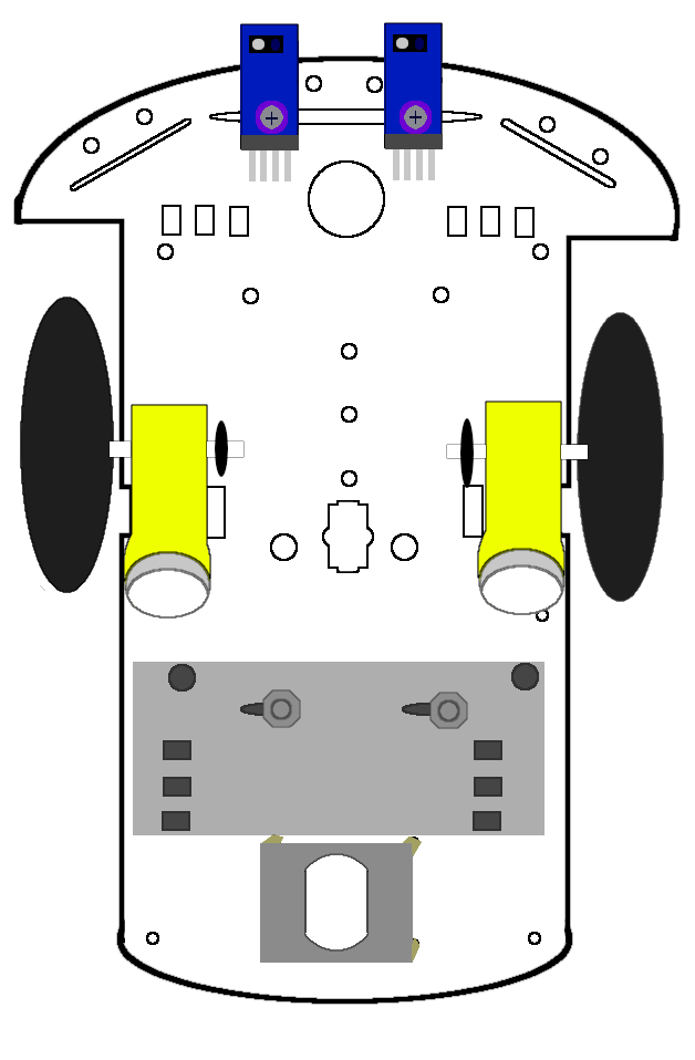
Once the standoffs are secure, the sensor modules can be mounted. With
the IR
LED and photoreceptor facing downwards, align the hole with the
standoff from
underneath the car,
and secure it to the standoff with the M3*5 bolt. Use a screwdriver to
secure
the bolt. Small pliers may be used to secure the nuts on the topside of
the
car.
A demonstration of this can be found in the video
below:
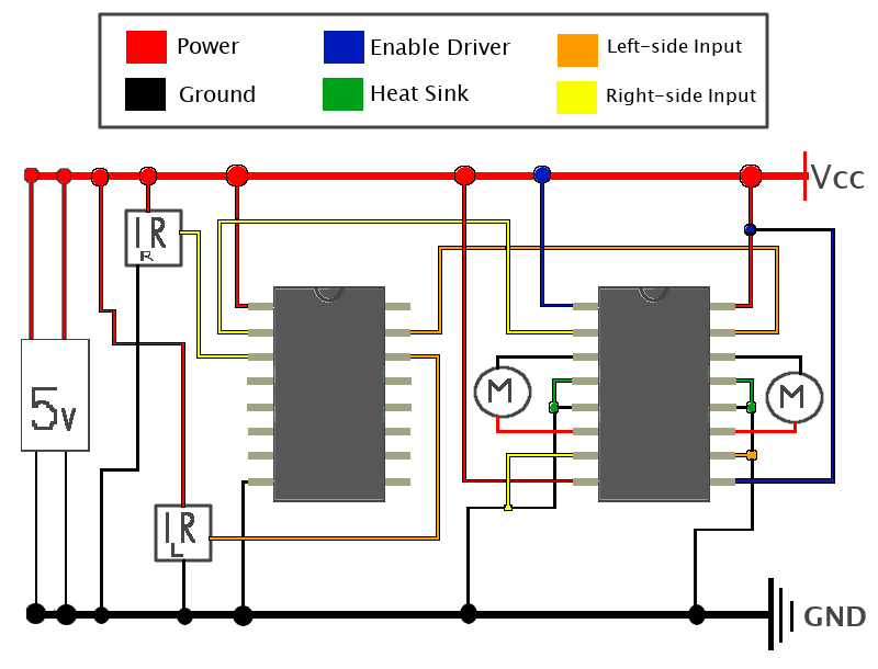
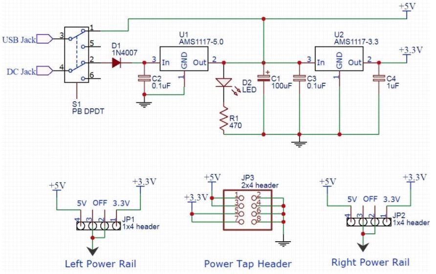
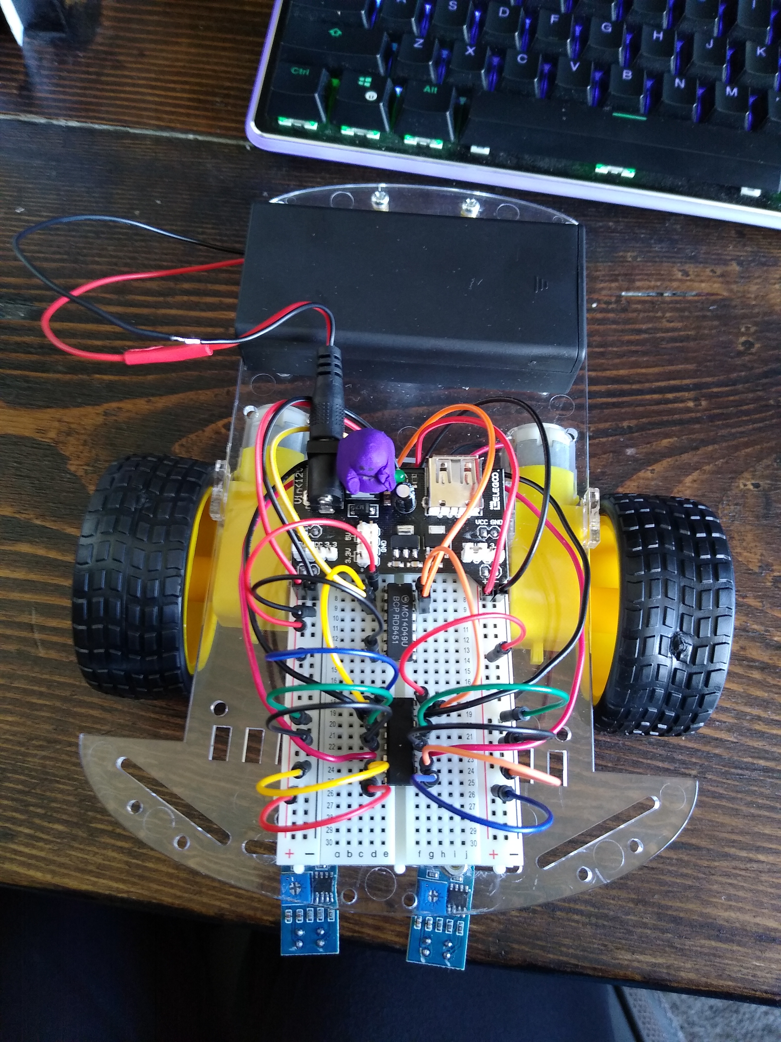
The circuit of the car will be as shown in the
figure below. The
details of the
IR sensor modules and power supply are not shown here,
as they are being treated as black boxes in this schematic.
The rectangle labeled "5V" represents the power
supply; The power supply is composed of the battery pack that holds two
3.7V batteries,
and a DC-DC converter. This converts a power supply of up to 12V down
to either 5V or 3.3V. We will be using the 5V option in this circuit.
We will be converting the 7.4V supply down to 5V to control the speed
of the motors.
The modules should have the pins labeled for you.
The pin labeled
"VCC" will power the module's circuit, and the pin labeled
"GND" will ground the sensor's circuit.
The pin labeled "DO" will send the output as a digital signal. The
pin labeled "AO" will output the signal as an analogue signal; we will
not be using this pin.
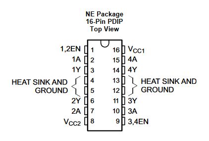
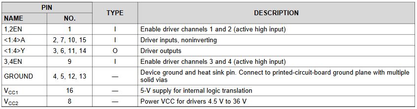
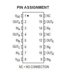
The pin-out maps of the inverter and driver are as shown in the figures below.
For the driver:
Here is a demonstration of the car following the
black lined track both clockwise and counter-clockwise: