Tasks 1-10
For the first task, the PicoBlaze MCU was used with the FPGA on the Basys3 board to control the LEDs when the
switches were activated. The demonstration video can be seen below in Video 1.
Video 1. This is a recorded demonstration of the LEDs responding to the switches via the Pico Blaze MCU and the Atrix-7 FPGA on the Basys3 protoboard.
Once the switches successfully controlled the LEDs with both the FPGA and the MCU, a square addition function was
implemented to the circuit. A recorded demonstration of this can be found below in Video 2.
Video 2 This is a recorded demonstration of the FPGA and PicoBlaze responding to the switches via the Pico Blaze MCU and the Atrix-7 FPGA on the Basys3 protoboard.
The next step was to write instructions in Assembly to have 0x13 added to the switch input, and the results were
displayed on the LEDs on the Basys3 board. A recorded demonstration can be found in Video 3 below.
Video 3 This is a recorded demonstration of the FPGA and PicoBlaze responding to the switches via the Pico Blaze MCU and the Atrix-7 FPGA on the Basys3 protoboard.
Once this was functioning properly, the assembly code was altered to display the value on the LEDs of the
the Basys3 board while holding the last two bits (LSBs) as 11. A recorded demonstration can be found in Video 4 below.
Video 4 This is a recorded demonstration of the FPGA and PicoBlaze responding to the switches via the Pico Blaze MCU and the Atrix-7 FPGA on the Basys3 protoboard.
Once this was functioning properly, the assembly code was altered to shift the swith input to the right by 1. A recorded demonstration can be found in Video 5 below.
Video 5 This is a recorded demonstration of the FPGA and PicoBlaze responding to the switches via the Pico Blaze MCU and the Atrix-7 FPGA on the Basys3 protoboard.
Once this was functioning properly, the assembly code was altered to jump the LED output as the first swith input is toggled. A recorded demonstration can be found in Video 6 below.
Video 6 This is a recorded demonstration of the FPGA and PicoBlaze responding to the switches via the Pico Blaze MCU and the Atrix-7 FPGA on the Basys3 protoboard.
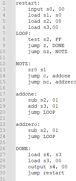
Once this was functioning properly, the assembly code was adjusted again to practice using multiple subroutines. A recorded demonstration can be found in Video 6 below.
Video 6 This is a recorded demonstration of the FPGA and PicoBlaze responding to the switches via the Pico Blaze MCU and the Atrix-7 FPGA on the Basys3 protoboard.
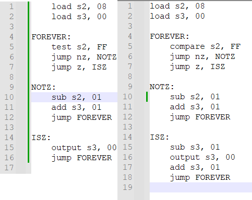
Once this was functioning properly, the assembly code was adjusted again to practice using the compare subroutines. A screen-snip of the assembly code using multiple subroutines is shown on the right, and the code with the change to achieve the same output
with the compare subroutine on the left can be found in Figure 1 below.