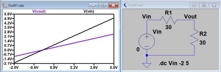
3. DC sweep
In DC analysis, the X axis will be a DC voltage other than 'time' in transient analysis.
In the following schematic, the circuit ran a DC sweep for the input voltage from -2 V to 5 V. The X axis will be the 'sweep' of the DV values for Vin, the Y axis is the voltages in terms of the input.
Implement this circuit using Spice code, show your simulation results in your report.
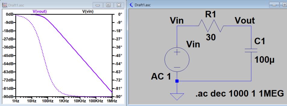
4. AC analysis (AC sweep)
In Ac analysis, the X axis will be 'frequency', the Y axis will be the amplitude. This is very powerful. You can use this analysis to test the bandwidth of the circuit.
'.ac dec 1000 1 1MEG' means the axis units are in decades of increment, plot 100 points per decade, starting from 1 Hz to 1MEG Hz.
Implement this circuit in Spice code, and report your results.
** hint: the AC source here can be coded as: 'Vin Vin 0 ac 1'
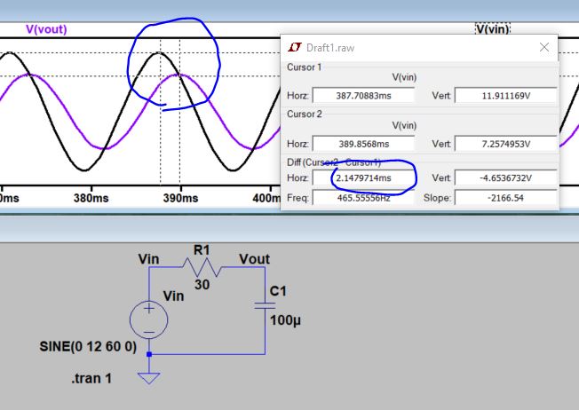
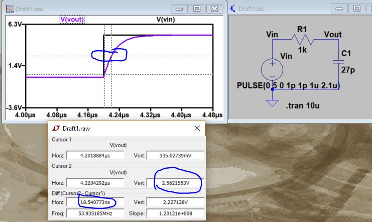
5. DC pulses
Now let's use DC pulses as the input voltage source to drive a capacitor.
Use the Spice code to implement the following circuit and then measure the time-delay of the circuit. Compare it to your calculation.
**hint: the pulse function means PULSE (LowVoltage HighVoltage Delay RisingTime FallingTime OnTime Period). The reason that the period is a little longer than the 'On' time is the rising edge and the falling edge of the pulse are also taking time even though they are short.
No need to build this cicuit on a breadboard.