Lab 5 The
Robot Car Line Follower (2-week lab)
Outcome
of this lab:
1.
Be able to design a driving circuit for DC motors.
2. Be able to use sensors and electrical circuits to solve real
problems.
3. Be able to design circuits using potoresitors, motor drivers, and Op
Amp
comparators.
Read the paper, make sure
you understand what's going
on before you start working on it.
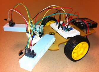
We will use an
infrared Radiation (IR) emitter and an IR receiver to
complete this task.
Watch the video here
on YouTube to understand the IR emittion and receiving mechanism
beofore you start. Our IR emitter and receiver are slightly different
but they will do the same job.
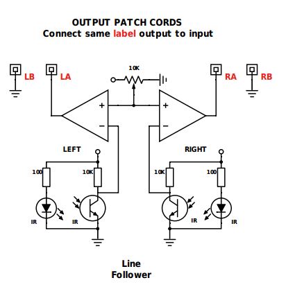
Refer to the
schematic below, make sure you understand it before you get started.
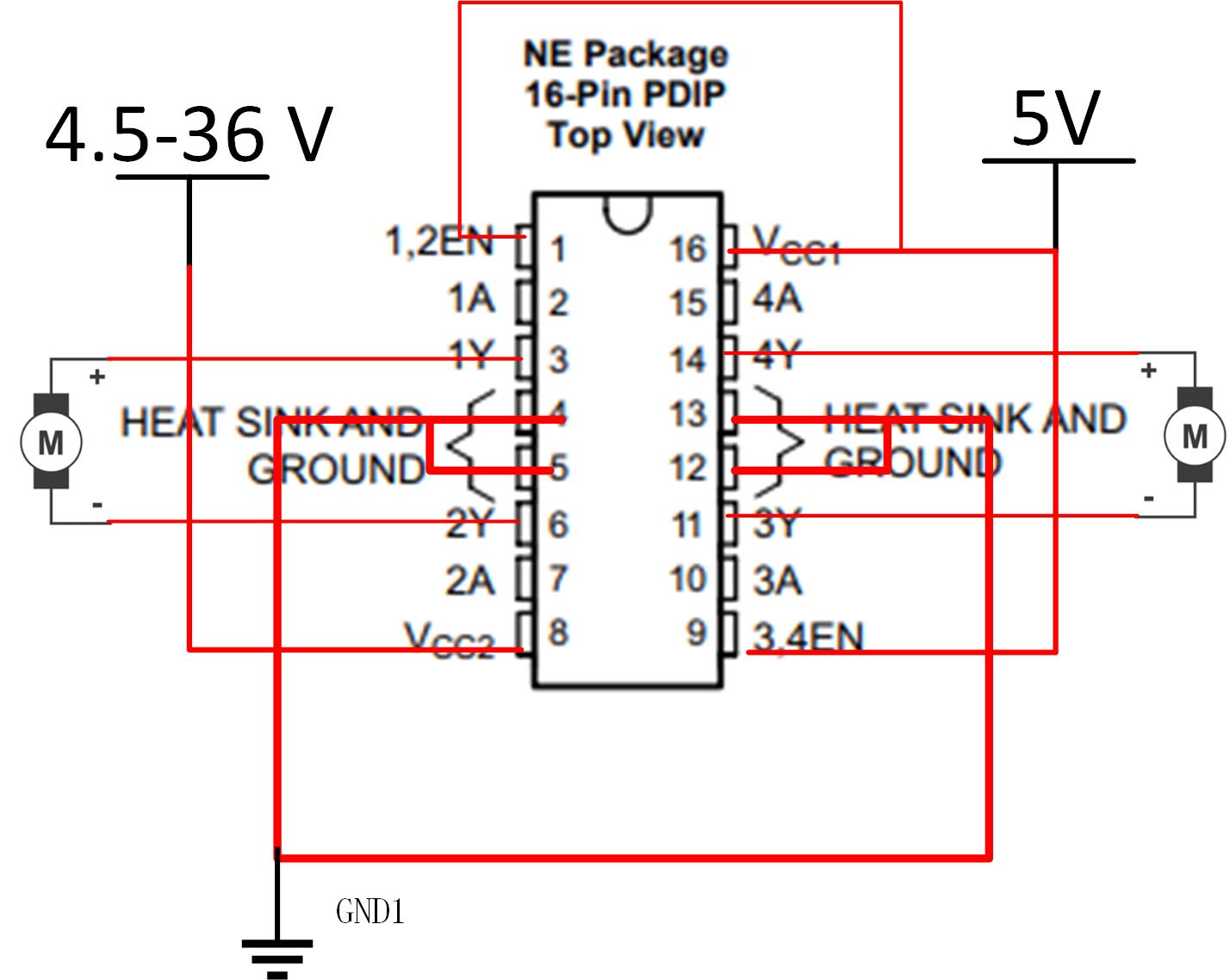
Pin Map of the motor driver:
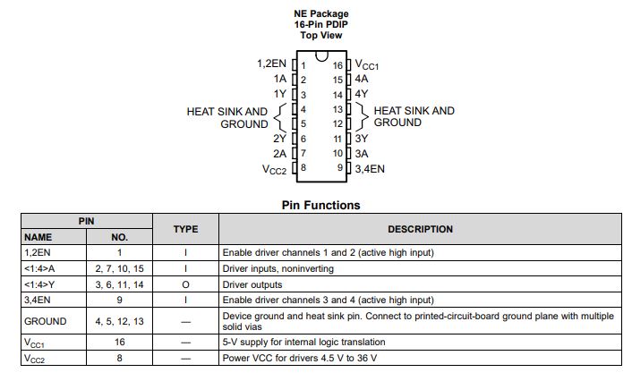
Useful snapshot from the datasheet:
In order to
follow the line:
When
light is received by the sensor on the LEFT side, which means
reflection received and the robot car is moving out of the RIGHT
boundary and need to turn RIGHT slightly. So the LEFT motor should be
turned on.
When
light is received by the sensor on the RIGHT side, which means
reflection
received and the robot car is moving out of the RIGHT boundary and need
to turn LEFT slightly. So the RIGHT motor should be turned on.
Feel free to refer to the lab
reports from last year for some ideas of how to get started if you
need. This lab is part of the 'Project' lab report in the past.
Follow the lab
report
guidelines
to avoid losing points.