Project:
A Smart Robot Car, Final
Report due: Dec 7, Friday 10 pm.
Outcome
of this project:
1.
Be able to design a driving circuit for DC motors.
2. Be able to use sensors and electrical circuits to solve real
problems.
3. Be able to design circuits using potoresitors, motor drivers, Op Amp
comparators, and 555 timers.
Grading
Criteria:
Task 1: 10 points
Task 2: 15 points
Task 3: 15 points
Task 4: 15 points
Task 5: 15 points
Report Writing:
30 points.
If
the demo on the bread board off the car works but the car is not able
to complete the challenge in real-life, you will receive 60% of the
credit in that task. Try to start this project as soon as possible in
the semester. Whenever you complete any of the tasks and show me the
results, you can receive the credit on that task. Do not wait until the
last minute of the semester to start this.
In
Fall 2017, Dr. Ryan Haaland used this robot kit, for the first time,
for the course project in his ENGR 201 Network I class. In the spring
of 2018, Dr. Megan Paciaroni used the same robot car kit, but replaced
and organized part of the old electronic compoments for her ENGR 201
class. Now, this is the third
time that this robot car kit will being used for ENGR 201. Bad pats of
the car body in the kits are replaced, disfunctional electronic
components are ordered and organized in the plastic cabinet. Please
being gentle when you use the components and put them back to
the drawer after the project is completed. Leave a Good mess to your
colleagues.
Let's start the instruction of this project.
Task
1: Introduction to the Kit (10 points)
This
project was published as a journal paper at American Journal of
Physics in 2017.
The PDF of this paper can be found here.
It has two supplementary materials being published at the same time:
Block Diagram, Circuit Schematics
Also, there is a video
shows the demo of the 'obstacle avoiding' function of the robot.
The total project has 4 tasks. They are 'Light Following', 'Line
Following', 'Obstacle Avoiding', and 'Edge avoiding'. Before we start
anything, please
read the paper for many times until you can understand the
circuits. You are almost 60% done after you understand the mechanisms
for each circuit, which means there is no magic about this in your mind
before you start, the remaining work is just to implement it!!
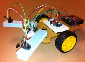
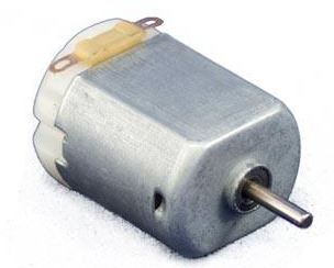
The robot car is driven by two DC motors mounted to the left and the
right wheel. The motors are the 'engine' of the car. A DC motor is
controlled by DC voltages, which means having DC voltages applied to
the two terminals of a DC motor:
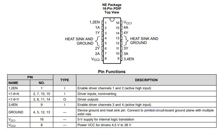
A DC motor draws a lot of current (50 - 100 mA). Regular
logic voltages such as 3.3 V or 5 V are not sufficient to drive a DC
motor efficiently. We need an individual power supply to provide enough
driving capability. A motor driver integrated circuit is usually used
to receive logic commands and convert it into real driving current for
motors. We will use L293D
for this project.
Read
the pin map and the table very carefully:
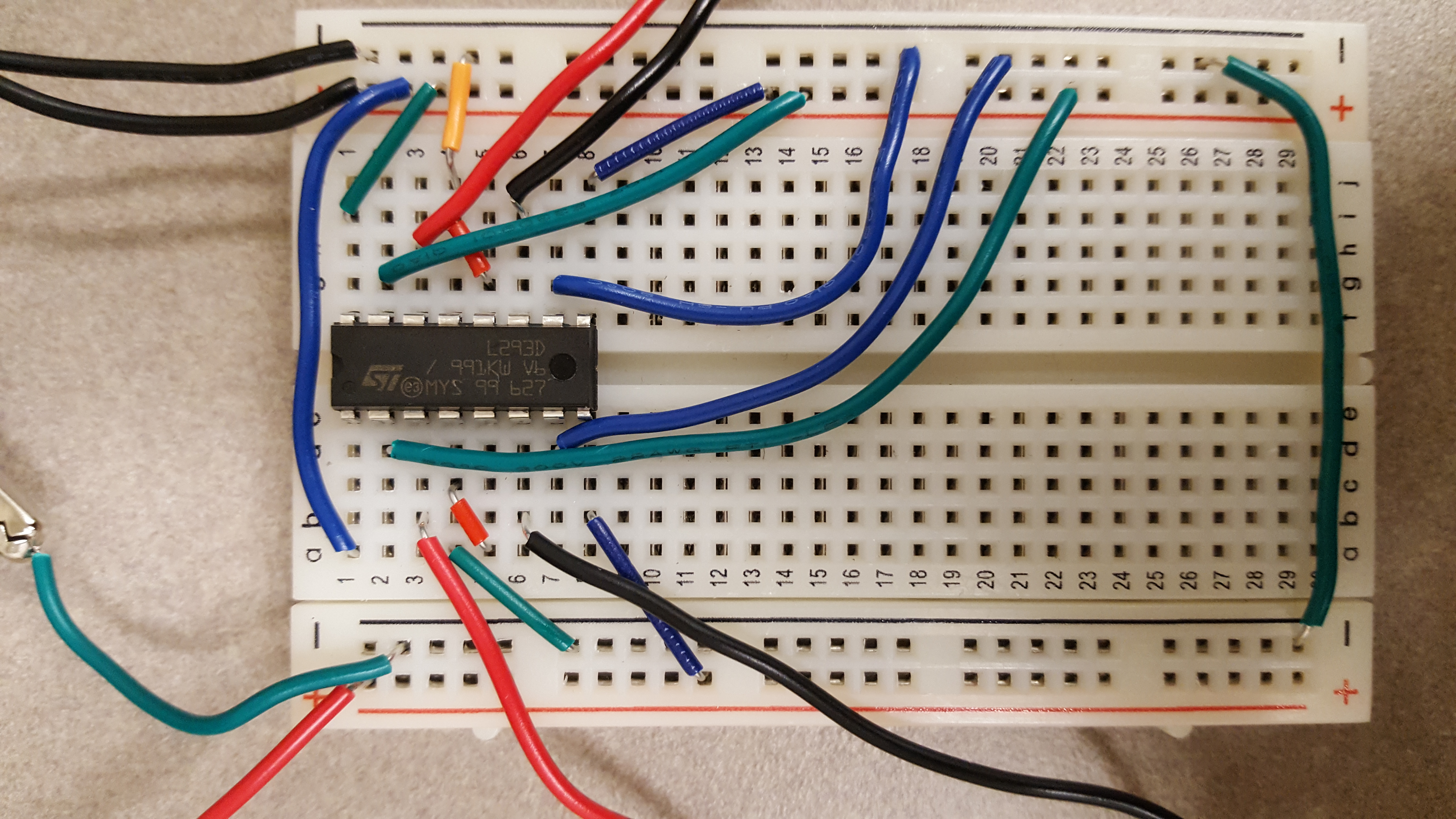
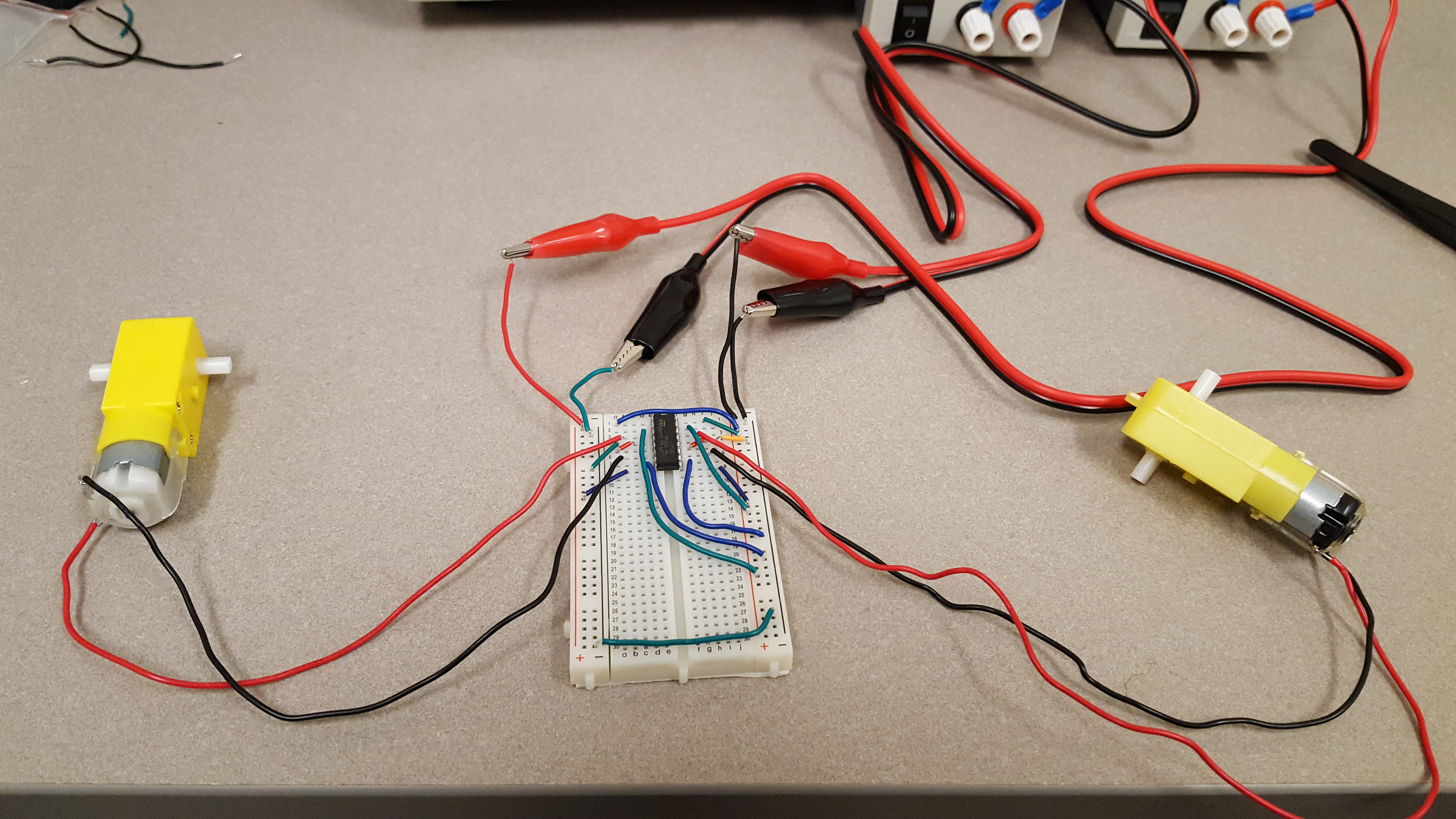
Any project like this, you should start from the very basic steps. The
first thing you want to test is if the L293D you have can drive a
motor. So you don't need to build everything on robot car yet, instead,
just build things on a breadboard, control the wires/inputs manually,
see if the motors run. By the way, try higher voltages see if the motor
will run faster.
The first test is just verify that you understand how the motor is
driven by L293D, and how to make the motor runs.
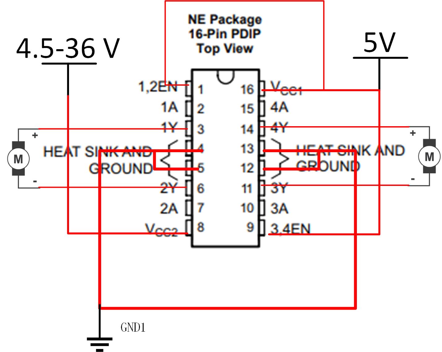
The real circuit on a breadboard:
Show your
results for Chapter 1 in your report. Make good records of every
successful step so you can at least get partial credit.
Task
2: Light Follower (Light Sensors
and Op Amp comparators) (15 points)
In this section,
you will build a prototype on a breadboard first, and
then implement it to the robot car.
Read this
specific section in the paper, make sure you understand what's going
one before you start. Again, the paper is here.
The Op Amp being
used here is LM741.
The schematic of
the circuit is:
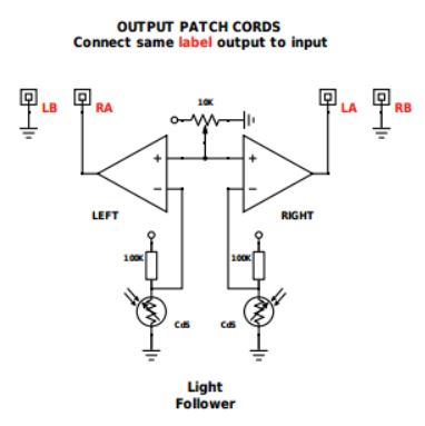
This schematic
does not show the power supply for the Op Amp, use 5 V
and GND for V+ and V-.
The
potentiometer is not required, you can use a voltage divider to
make a 2.5V reference voltage for this. Use two 10k resistors to divide
your 5V into 2.5V.
The power supply
for the resistor and the photocell is 5V.
In order to
follow the light:
When
light is received by the sensor on the LEFT side, it should activate
the motor that controls the RIGHT motor to make a slight RIGHT TURN.
When
light is received by the sensor on the RIGHT side, it should
activate the motor that controls the LEFT motor to make a slight LEFT
TURN.
Test this
circuit on the
breadboard, and implement it to the robot car. If your robot car can do
the 'Light Following' job, you get 15 points for this chapter. Record
the video use your phone for your report in the future (save it
somewhere securely). Show me your robot works in person for the credit.
Task
3: Line Follower (15 points)
Read this
specific section in the paper, make sure you understand what's going
one before you start. Again, the paper is here.
We will use an
infrared Radiation (IR) emitter and an IR receiver to
complete this task.
Watch the video here
on YouTube to understand the IR emittion and receiving mechanism
beofore you start. Our IR emitter and receiver are slightly different
but they will do the same job.
Look at the
schematic below, make sure you understand it before you
start.
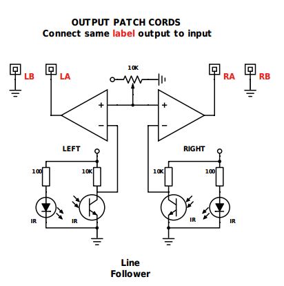
In order to
follow the line:
When
light is received by the sensor on the LEFT side, which means
reflection received and the robot car is moving out of the RIGHT
boundary and need to turn slightly RIGHT. So the LEFT motor should be
turned on.
When
light is received by the sensor on the RIGHT side, which means
reflection
received and the robot car is moving out of the RIGHT boundary and need
to turn slightly LEFT. So the RIGHT motor should be turned on.
When I was doing
the IR part, it was not working for me for the first time. I used
multimeters to
test the voltages at all the nodes and found that either the emitter or
the receiver was not working properly. I replaced the receiver first,
it
didn't fix the problem. Then I was about 99% that the emitter is
broken. I replaced the emitter, the circuit started working.
Please have the
same
test done before you put things on a robot car. Once you are confident
about your circuit, connect them to the robot car. Use black tapes to
make a zig-zagged
line on the table. Let your robot car follow the line and record video
use your phone for your report in the future (save it somewhere
securely). Show me your robot works in person for the credit.
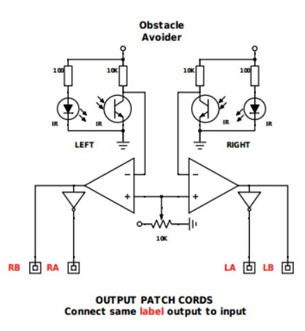
Task
4: Obtacle Avoider (15 points)
This task has
only a few simple additions to the Line Follower:
1. Change the
logic input of the motor driver to 1 0, or 0 1, instead
of 1 0, or 0 0. So the motor will always run but just changing
directions when reflection light is detected.
2. Add inverters
(MC14049) to the
output of the Op Amp.
The schematic
is:
Please
have the
same
test done before you put things on a robot car. Once you are confident
about your circuit, connect them to the robot car. Repeat the same
results achieved in the video from the original inventer/author of this
kit. Again, the video can be found here.
Demo your result to me for the full credit.
Task
5: Edge Avoider (15 points)
This is the last task of this project.
Again, read the section on the paper to understand the idea of this
design.
The point is, a sharp trigger based on the optical signal is not long
enough to turn the car away from the edge, which means the car will
still drop.
We need to make the response longer to drive the car away from the
edge. The 555 timer will be
used here for this purpose.
The schematic of the circuit:
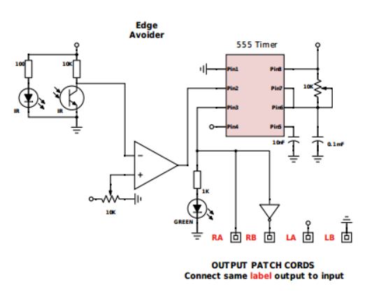
I didn't use the potentiometer shown in the circuit. I just put a 10 k
resistor between pin 6 and pin 8.
0.1 nF = 100 uF, this is an electrolytic capacitor. The LONGER pin is
the positive terminal, which should be connected to the resistor. The
shorter pin should be grounded. This is important.
The Green light LED is not necessary.
You need to change the resistance between pin 8 and pin 6 to change the
time period of the reversing turn on the wheel when 'out of boundary'
is detected.
Please
have the
same
test done before you put things on a robot car. Once you are confident
about your circuit, connect them to the robot car. Repeat the same
results achieved in the video from the original inventer/author of this
kit. Demo your result to me for the full credit.
-------This is the end of the project.
Follow the lab
report
guidelines
to avoid losing points.