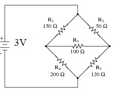
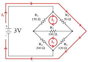
Calculate (use the mesh current method), simulate, and verify on board for all the voltages and current in the following circuit:
Unbalanced Wheatstone Bridge:
The Wheatstone bridge is used in two ways: (1) to measure the value of an unknown resistor by comparison to standard resistors, and (2) to detect small changes in a resistance transducer. Let's use this bridge to build a 'Shadow Detector' using an LDR.
A photoresistor (or light-dependent resistor, LDR, or photo-conductive cell) is a light-controlled variable resistor. The resistance of a photoresistor decreases with increasing incident light intensity; in other words, it exhibits photoconductivity. A photoresistor can be applied in light-sensitive detector circuits, and light-activated and dark-activated switching circuits.
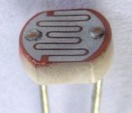
An LDR
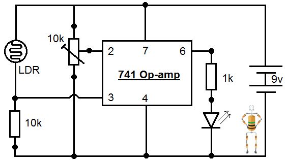
Parts Required & Circuit Diagram:
10k potentiometer,
10k & 1k LDR
741 Comparator op-amp
LED
9V voltage source
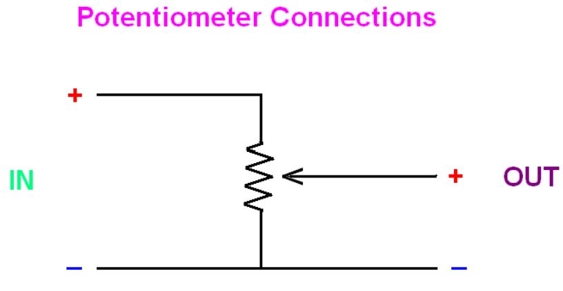
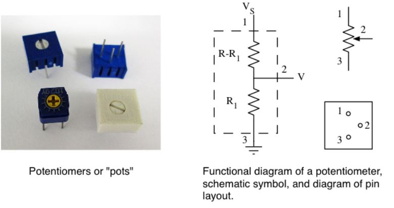
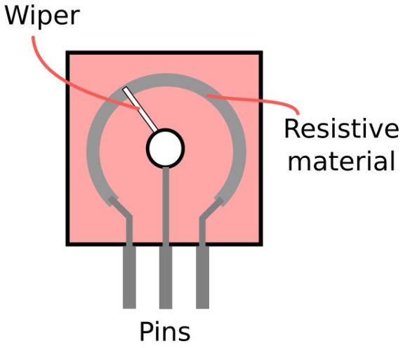
A potentiometer is an electrical component/device that can be adjusted to provide an on-demand resistance (in a certain range) in a cicuit.
Picutres of potentiometers and schematic of them can be found in the following figures:
The Light sensor circuit can be found in the following figure. Probably most simple and interesting circuit to play with. It can be configured as either shadow detector or Light detector, which means it can detect the intensity of light. Right now in the circuit diagram it is configured as a Light Detector, that means the LED will turn on when we show a bright light over LDR. We can change this circuit as Shadow Detector by simply swapping the pins 2 & 3 of 741 Comparator IC, and then LED will turn on when LDR is dark. In this circuit, please make sure that pins no 1,5 & 8 are not connected and left idle. Pin 6 is output pin. In the circuit it is connected to an LED via 1K resistor, but you can also connect a transistor to turn on a relay, motor or any other output.
Show the results in your report.
** The shadow detector circuit is borrowed from 'Rookie Electronics', at http://rookieelectronics.com/sensor-projects-light-sensor.
** Report your results (with figures and texts) on the website.