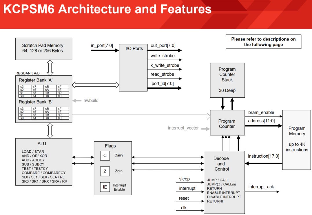
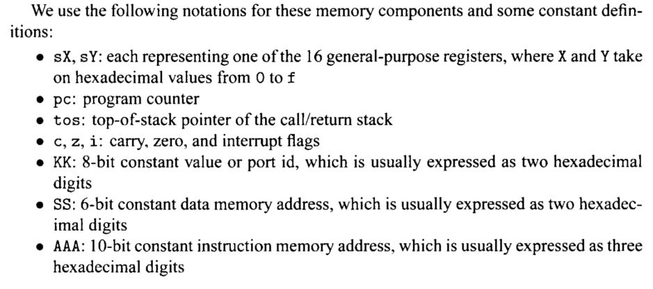
The architecture and the
instruction set introduced below are for KCPSM3. For the difference
between these two versions, you can refer to the official KCPSM6 User Guide.
The following snapshots are from Pong Chu's book: FPGA Prototyping By
Verilog Examples - Xilinx Spartan - 3 Version. The contents may be for
the old version KCPSM3 but it is very similar to
There are two assembler programs for PicoBlaze: KCPSM3 (we will use the newer release - KCPSM6) from Xilinx and
PBlazeIDE from Mediatronix.
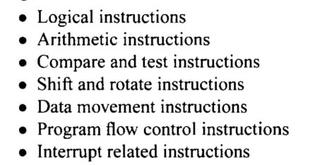
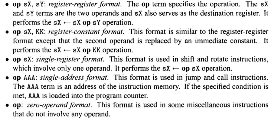
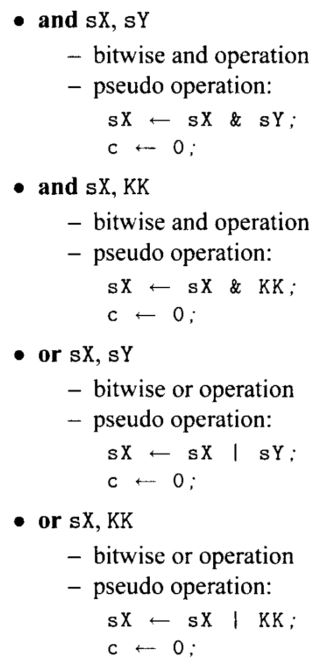
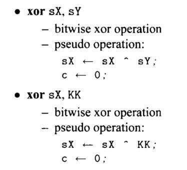
Logic Instructions:
There are
six logical instructions, which support
the and, or, and xor operations. An
instruction performs bitwise logical operation between two registers or
between one register and a constant. The carry flag, c, is always cleared.
The zero flag, z, reflects the result ofthe operation. The mnemonics,
brief descriptions, and pseudo operations of these instructions are:
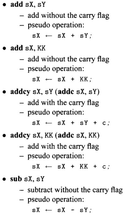
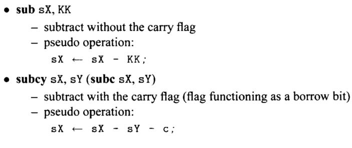
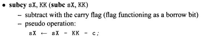
Arithmetic Instructions:
There are eight
arithmetic instructions, which support
addition and subtraction with or without the carry
flag. The carry flag, c, and the zero flag, z, reflect the result of
operation. The mnemonics, brief descriptions, and pseudo operations of
these instructions are:
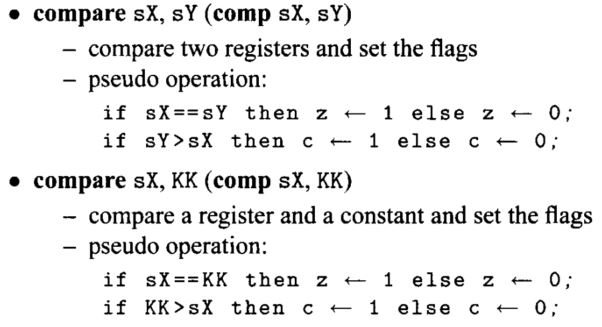
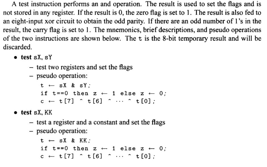
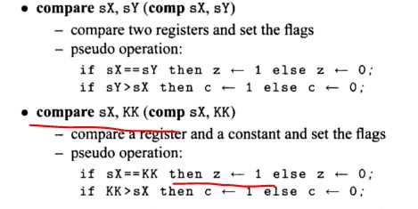
Compare and Test Instructions:
sX == sY, zc: 10 sX < sY, zc: 01 sX > sY, zc: 00
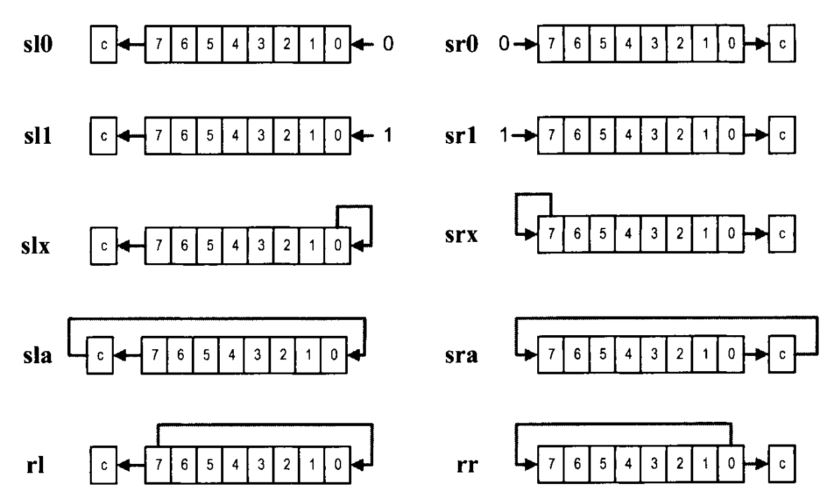
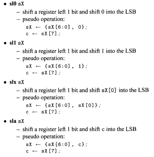
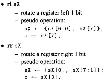
Shift and Rotate Instructions:
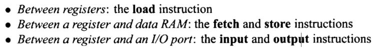
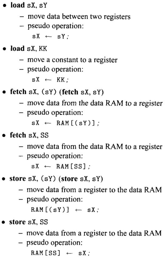
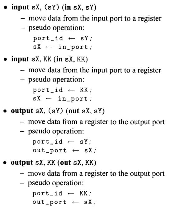
Data Movement Instructions:
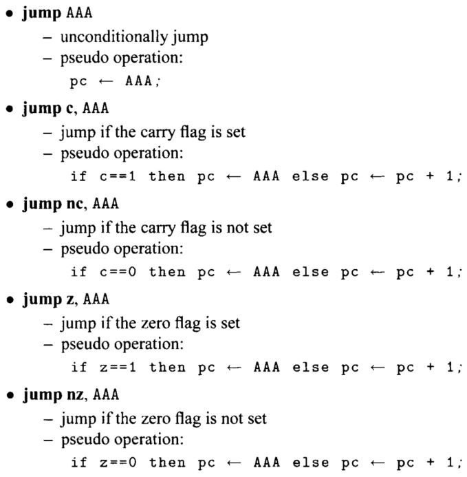
Program Flow Control Instructions:
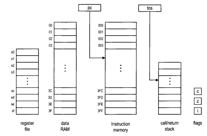
In PicoBlaze, the program
counter indicates where to fetch the instruction. By default, the
execution proceeds to the next address in the instruction memory and
the program counter is incremented implicitly (i.e., pc t
pc + 1).
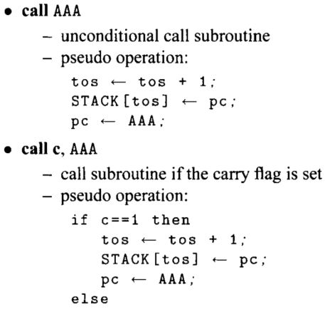
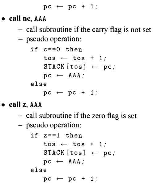
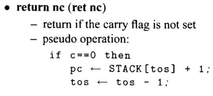
The jump, call, and return
instructions can explicitly load a value to the program counter
and modify the program flow. These instructions can be
executed unconditionally or conditionally based on the
values of the carry and zero flags. A jump
instruction loads a new value to
the program counter if the corresponding
condition is met. The program execution changes
the regular flow and branches to the new address. The program
flow continues normally after this point. The mnemonics, brief
descriptions, and pseudo operations of these instructions are shown
below. Recall that AAA is for the 10-bit instruction memory
address and pc is for the program counter.
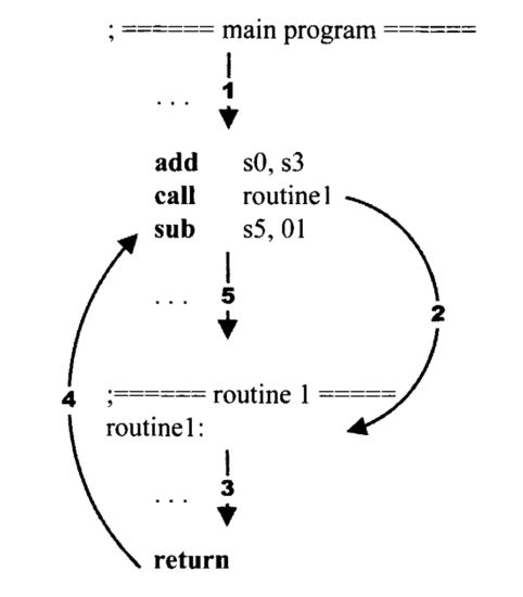
The call and return
instructions are used to implement a software
function. When a function is called, the
processor suspends the current execution
and branches to the corresponding routine. When the
routine computation is completed, the processor returns to the
suspended point and continues the execution. Like a jump instruction, a
call instruction loads a new value to the program counter if the
corresponding condition is met. In addition, it also saves the
current value of the program counter in a special buffer, known as the
stack. The new address represents the starting point of a
routine. The routine should include a return
instruction in the end.
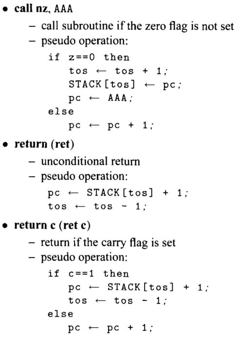
PicoBlaze allows nested
function calls, which means that a function can be called within
another function. To support this feature, a stack, which is a
last-in-first-out buffer, is used to store the program counter's
values. In this buffer, the address of the newest call is pushed
to the top of the stack (i.e., the "last-in"). Assume that this
routine does not contain other function call inside. It will be
completed first and the saved returned address is on the top of the
stack. It should be popped from the stack (i.e.,
"first-out") to resume the previous execution. PicoBlaze
provides a 3 1 -word stack for the nested call and return operations.
The mnemonics, brief descriptions, and pseudo
operations of the call and return in- structions are shown
below. Recall that t o s is for the top-of-stack
pointer. The STACK [ ] notation represents the content of the
stack.
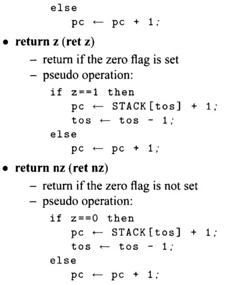
Interrupt Related Instructions:
Interrupt is
another mechanism to alter program execution
and its detail is discussed in Chapter
18. Unlike the jump and call instructions, it is initiated from an
external request. When the interrupt flag is enabled and the interrupt
request is asserted, PicoBlaze completes execution ofthe current
instruction, saves the address ofthe next instruction in the
call/return stack, preserves the cany and zero flags, disables the
interrupt flag, and loads the program counter with 3FF, which is the
starting address of the interrupt service routine. PicoBlaze has
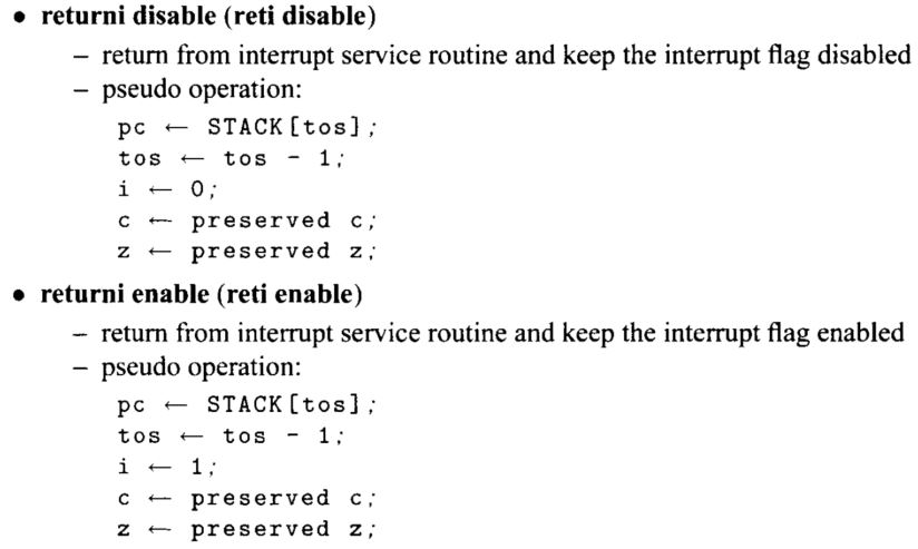
two return-from-interrupt instructions, which
resume operation from the interrupted location. It
also has two instructions that enable and disable the interrupt request
by setting or clearing the interrupt flag, i. The mnemonics, brief
descriptions, and pseudo operations of these instructions are:
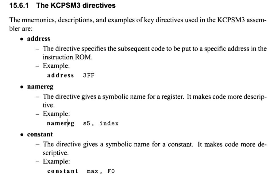
Assembler Directives:
An assembler directive
looks like an instruction in an assembly program. However,
it is not part of the microcontroller's instruction set but
is used to help program development. As its name suggests, a
directive "directs" the assembler to perform a specific
task, such as defining a constant or reserving data space.
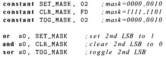
2. PicoBlaze Assembly Code Development
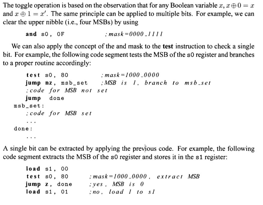
The following code segment shows how to set, clear, and toggle the second LSB of the SO register:
3. The workflow of SoC design using KCPSM6 and Basys 3
KCPSM - constant (K) coded programmable state machine. The KCPSM6
module is the PicoBlaze processor.
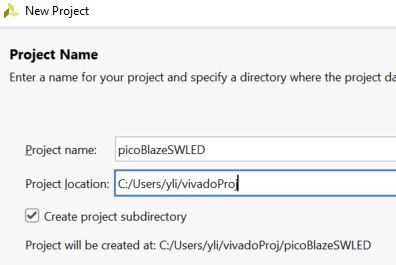
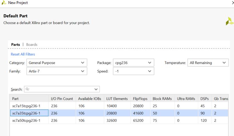
Create a new project in Vivado.
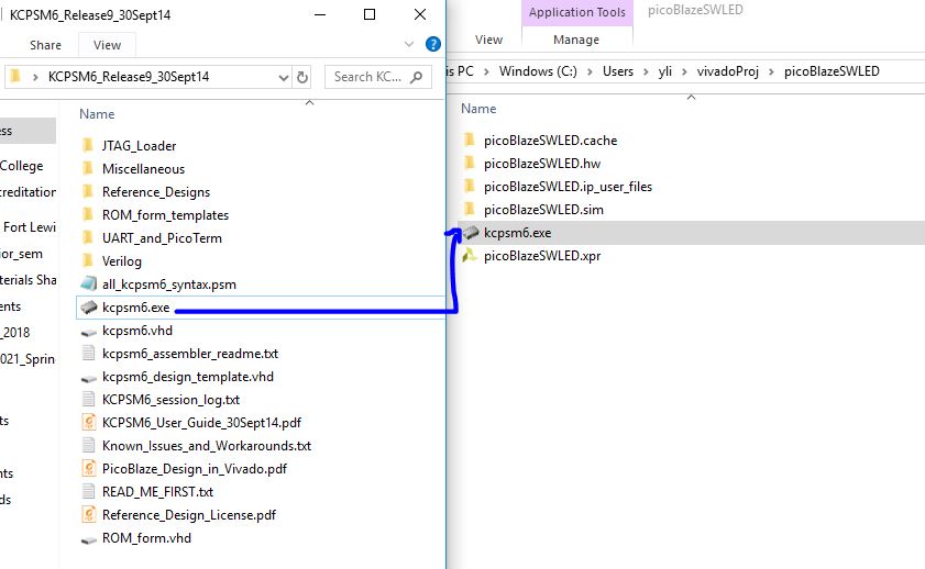
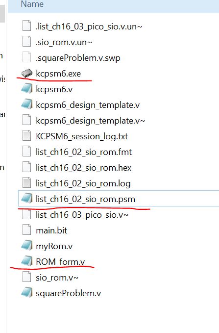
Copy the assembler kcpsm6.exe
to the project folder. This exe file is used to convert the assemly
conde into a ROM.v code for your project.
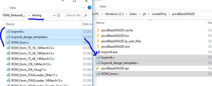
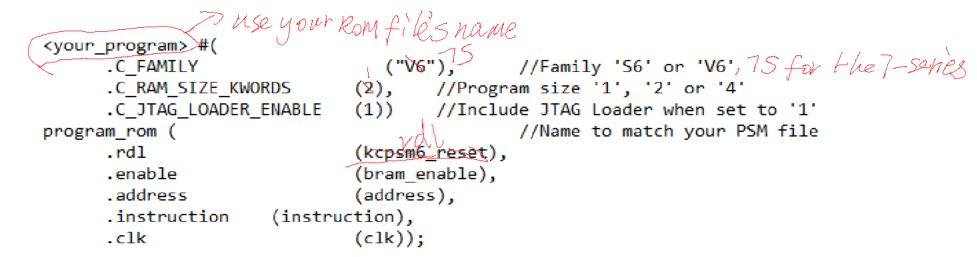
In the Verilog subfolder,
copy kcpsm6.v, kcpsm6_design_template.v, and ROM_form.v to the project
folder. kcpsm6.v is the HDL of the PicoBlaze core;
kcpsm6_design_template.v is not a desiign file, it contains examples
and code blocks for your design; ROM_form.v determines the compiled ROM
file to be a .v file but not a .vhd file. If you program using VHDL,
you need the ROM_form.vhd to be in this folder.
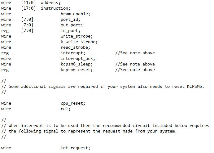
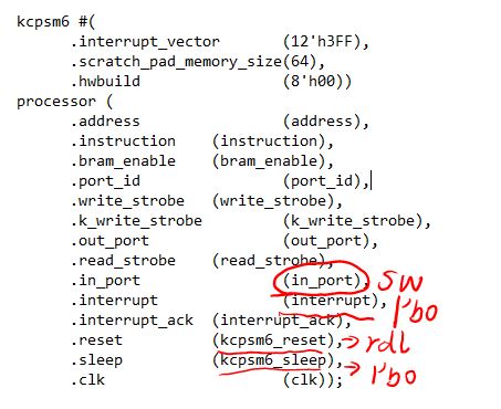
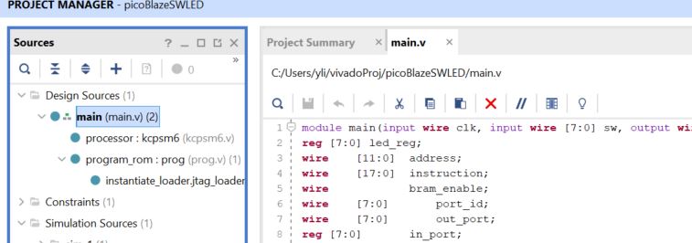
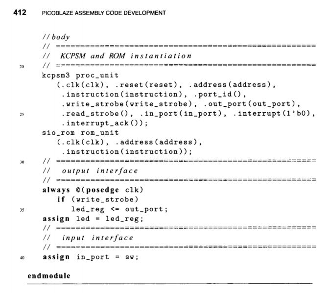
Create a main.v file as the
top level of the design, copy/paste the following code blocks from the
kcpsm6_design_template.v file to your main.v file.
For the behavioral part, you can use the following code:
Now, the only missing piece of the main.v file is the port declaration, please complete it on your own.
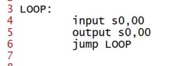
The purpose of this project
is to use switches [7:0] to turn on/off the corresponding leds. The following program was named as
prog.psm. You can use gvim to edit it.
The following script receives sw inputs from in_port number 0 and send it directly to the output 'out_port' number 0 as well.
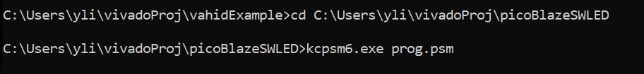
Save this file in the project
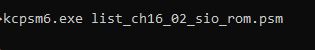
folder (important). In command line, enter the folder using 'cd <PATH> to the
folder', then use 'kcpsm6.exe prog.psm'.
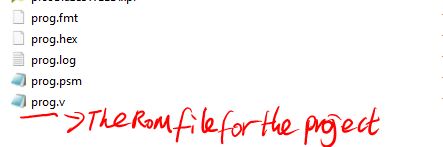
It generates the ROM.v file for the project.
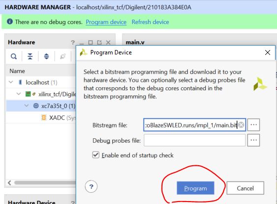
Add these design sources to the project and run synthesis, implementation, and generate bitstream respectively.
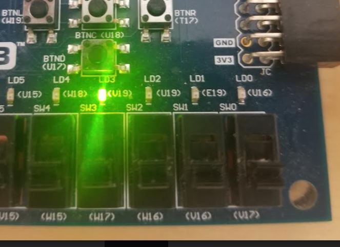
Download the bitstream file to your Basys 3 board, you should be able to see the switches control the LEDs.
4. The Square Problem
There is an interesting problem in Chapter 16 of Pong Chu's textbook - The square problem. Please read it through. (PDF)
To implement it on your Basys 3 board using the KCPSM6 compiler you need to do the following:
1. The assembly code is compatible with both KCPSM3 and KCPSM6 so
directly put it in the same directory with kcpsm6.exe and ROM_form.v: (the three files)
Then compile it in your command window
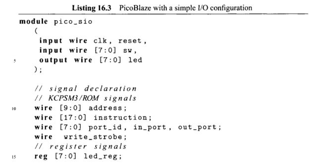
The top module in Pong Chu's book doesn't work for KCPSM6. There are
many issues with it, for example, the instruction address should be 12
bits but not 10 bits. It should be 'wire [11:0] instruction'. There are
many other issues so I recommend you use the kcpsm6 design template for the port declaration. Definitely use kcpsm6.v as the CPU core.
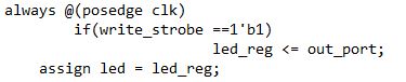
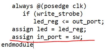
In the end of the top module, you can use the following code:
It uses the 'assign' funcion so on the top of the module when you declare in_port, it should be 'wire' but not 'reg'.
Here is the demonstration of the implementation:
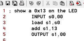
5. Assembly example: adding a 0x13 to the LEDs
The following program load 0x13 to the input port and send 0x13 to the LEDs.
Here is the result:
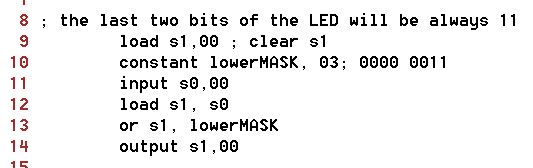
6. Assembly example: use the MASK
When you rerun the assembly file, please do the following to avoid potential glitches: (this applies to all the following tasks)
1. delete the prog.v file (the instruction memory file) before you recompile the new assembly code.
2. reload the prog.v file in your Vivado (remove the current one, and add the new one from add design sources).
The result:
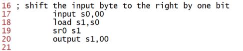
7. Assembly example: shift the sw input to the right by one bit
Results:
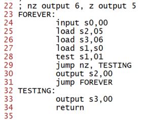
8. Assembly example: use jump, return, and load instructions
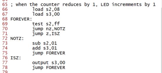
9. Assembly example: practice with multiple subroutines
10. Assembly exapmle: use the 'compare' instruction instead
Given the following explanation of the 'compare' instruction, revise the assembly code above to achieve the same result.
11.
Assembly programming task - design an assembly code to show the number
of switches that are ON on the LEDs in the binary form. The results must be able to show on LEDs without reprogramming the FPGA.
Demo video:
----------------- Tasks:
Repeat the work in Section 3
- 11 in this tutorial. If the Section asks you to complete something,
please complete it. Show the code and demo videos for credits.