The video graphics array (VGA) is a display standard used in the CRT
and LCD monitors. The Basys3 board has a VGA port
In the VGA, the display is formed of pixels (picture elements). These
are grouped into horizontal lines. Horizontal lines placed on the
screen form a frame. Therefore, a pixel location has both horizontal
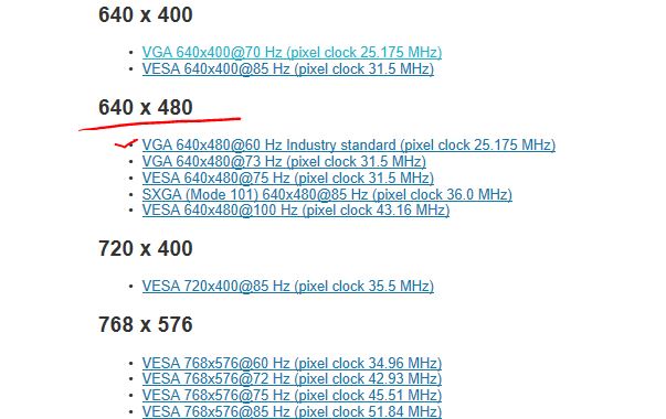
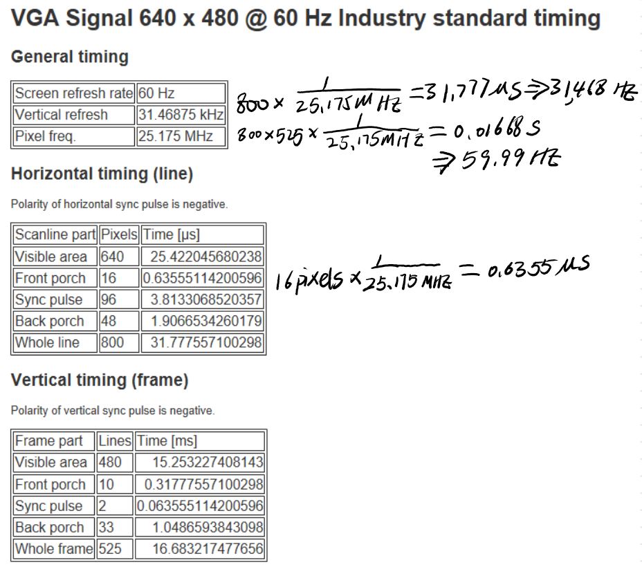
and vertical coordinates. One standard VGA display size is 640 × 480
pixels. This should be read as follows. The display is formed of 480
horizontal lines each holding 640 pixels.
The time needed to display a single pixel is determined by a pixel
clock. Hence, pixels in a horizontal line are displayed by the
successive clock signals. When end of the line is reached, the display
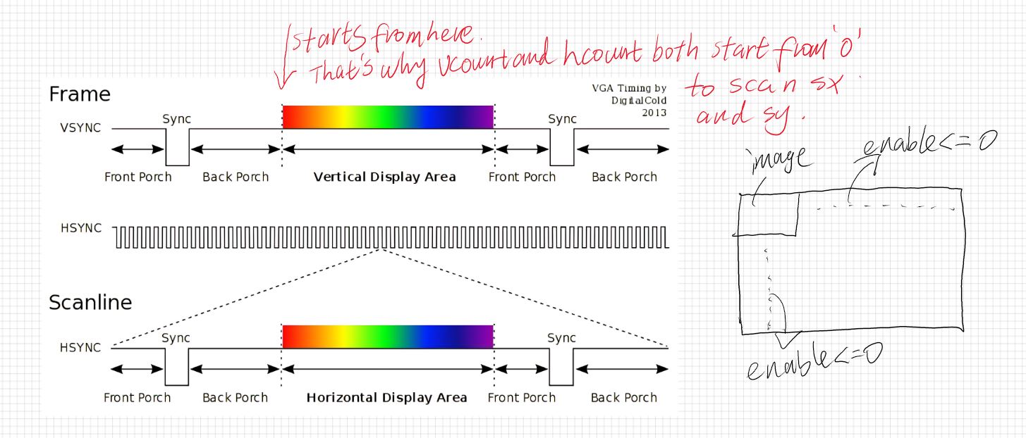
should continue with a new line. This is set by the horizontal
synchronization signal. When all lines in a frame are displayed, a new
frame should be formed. This is set by the vertical synchronization
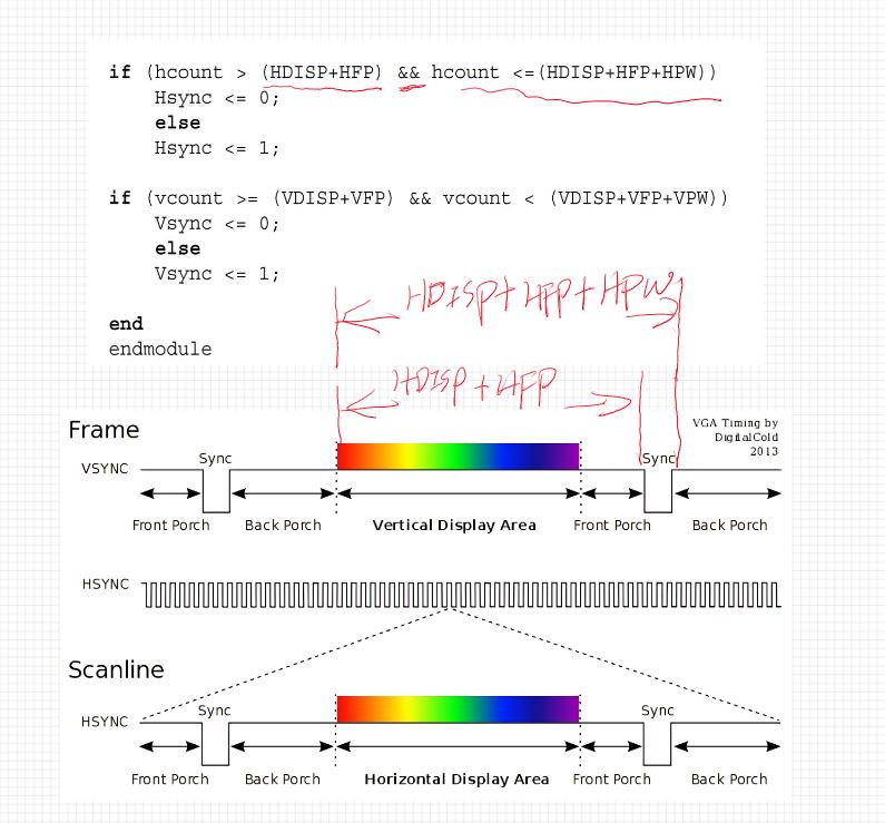
signal which also defines the refresh rate of display. The horizontal
and vertical synchronization signals depend on pixel clock by
definition. Moreover, the monitor needs some time before applying
horizontal and vertical synchronization signals. This is called front
porch. Similarly, we should wait for a certain amount of time after
displaying pixels in a horizontal line and frame. This is called back
porch.
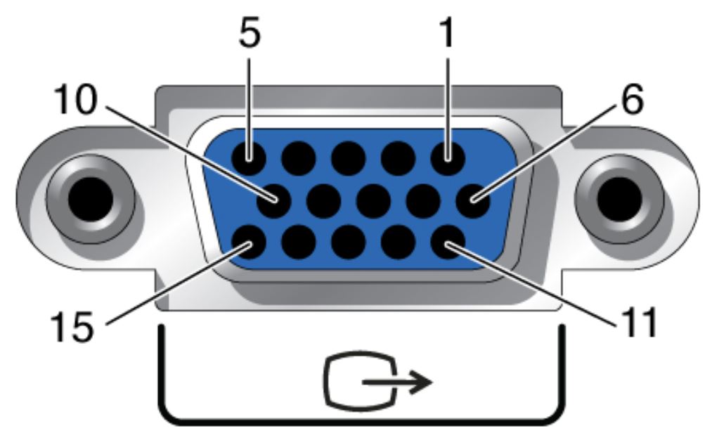
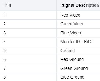
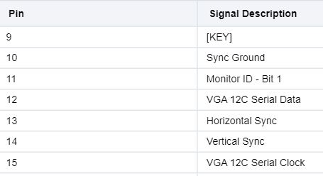
Every pixel has red, green, and blue (RGB) values in the VGA. As
mentioned in Chap. 3, the VGA connector on the Basys3 board allows
these RGB values to be represented by at most 12 bits. In this
scenario, the RGB values get four bits each. Hence, a pixel can have
one of 2^4 × 2^4 × 2^4 = 4096 different colors. One can also use eight
bits to represent the RGB values. Then, the RGB values get three,
three, and two bits, respectively. Hence, a pixel can have one of 2^3 ×
2^3 × 2^2 = 256 different colors.
Read through this PDF to understand the VGA
protocol.
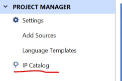
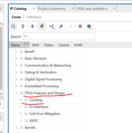
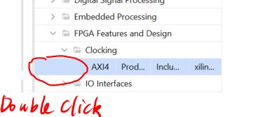
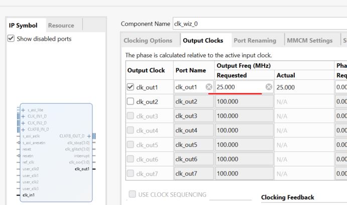
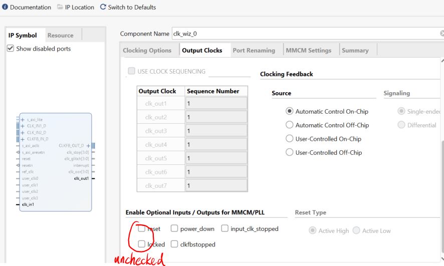
Create a clock generator module using the IP Catalog:
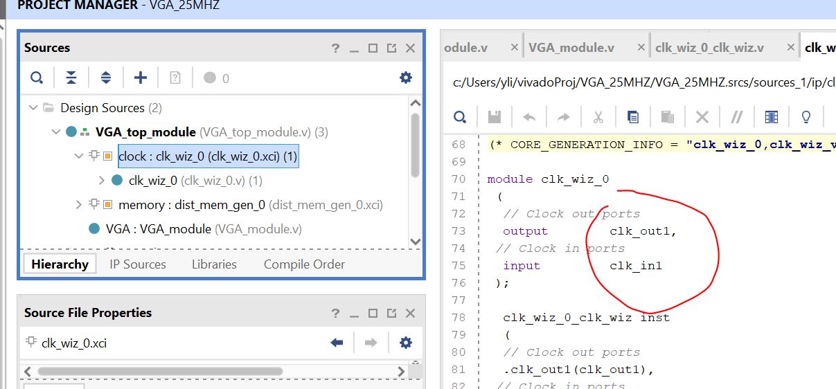
After the clock module is created, double click it in the source list.
You can find the order of the ports in the module is 'output, input'.
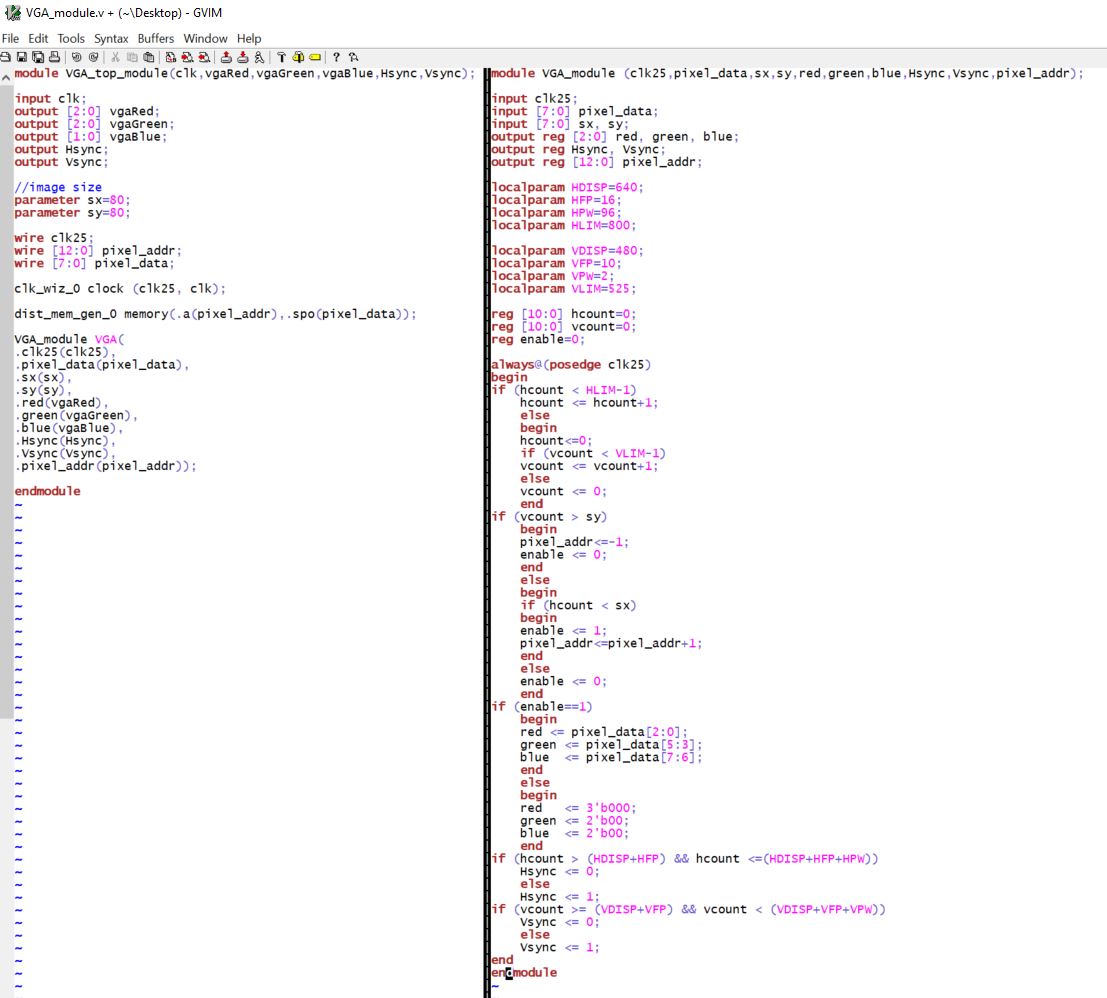
In this case, the example code of the top module from the textbook
didn't do wrong in instantiating the clock module:
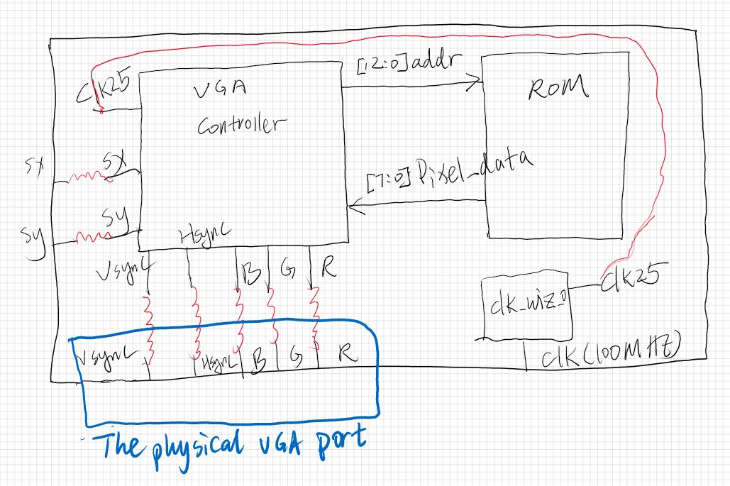
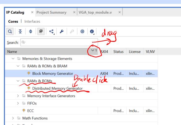
Create a distributed ROM to
store the image file. Different from the Block ROM we used in the
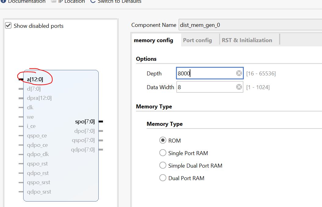
previous chapters, the distributed ROM doesn't have a clock input.
The depth doesn't have to be
8000. I opened up the test_image.coe file in gvim and find that it only
has 6000+ lines. I used 8000 as the depth which needs 13 bits of
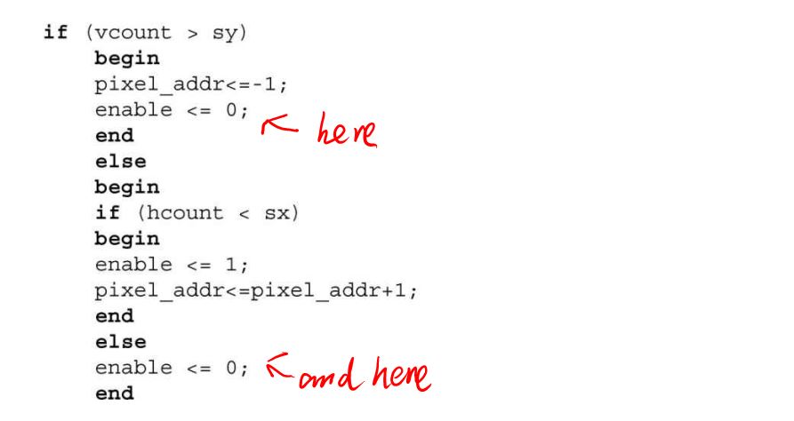
address. This is in line with the 'reg [12:0] pixel_addr' variable
defined in the VGA controller module.
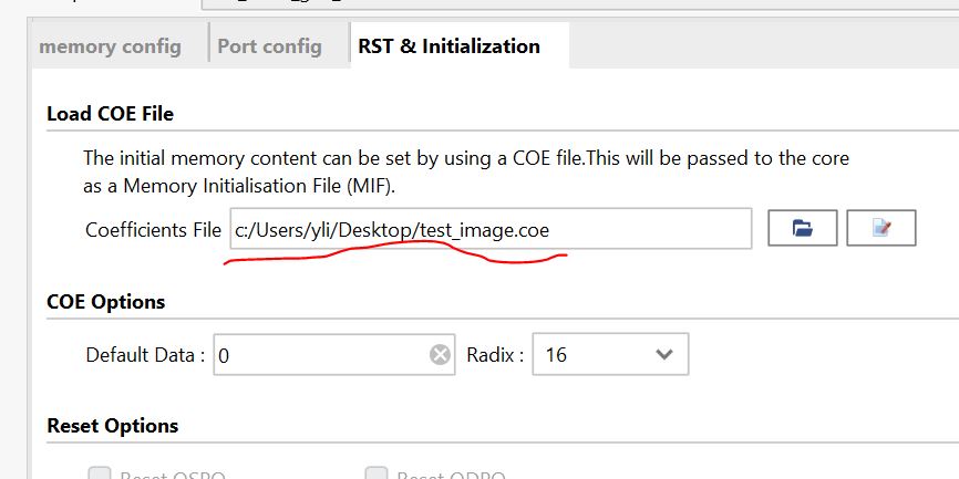
Don't forget to load the image file. Here is the image file.
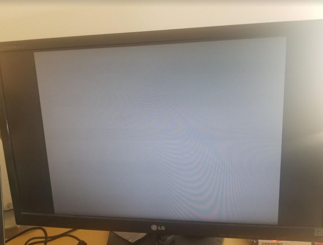
It was able to show the image on a monitor:
3. Modify the code
Task 1:
Change the code to display a blank white background on the monitor. You
must use all the 4 bits for each color to show an accurate RGB color on
the monitor. The RGB chart can be found here. For white, it is simply 4'b1111 or 4'hF.
Task 2:
Similar to Task 1, switch between R, G, and B, three solid colors, the interval of color change is 1 second.
--------------------------------- Task 1: Repeat the work in Section 2 (40 points) Task 2: Complete the two tasks in Section 3 (60 points).