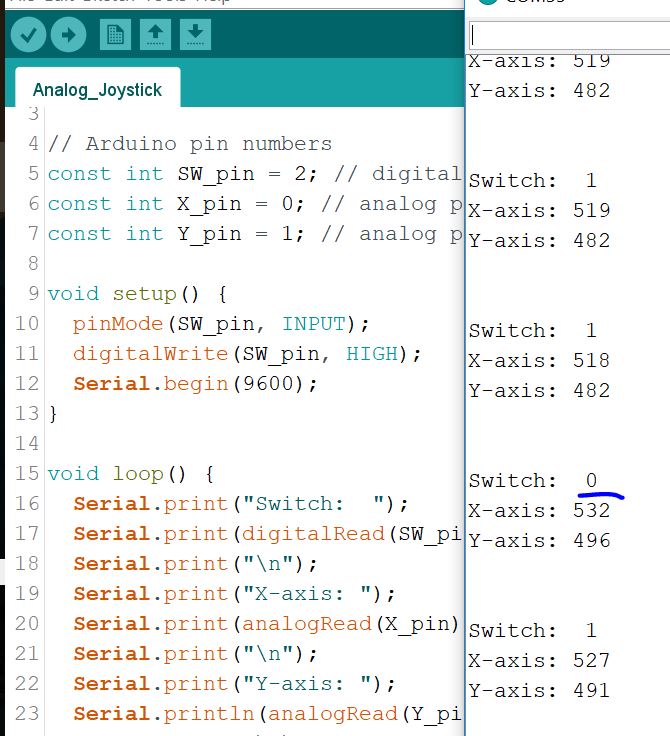
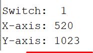
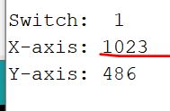
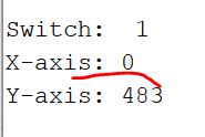
Open the serial monitor you will see the three readings, the switch,
and the two axes.
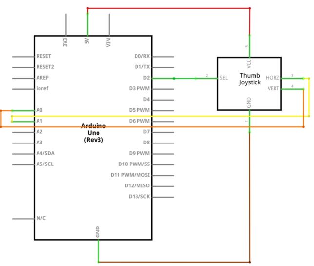
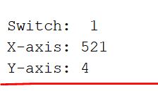
So the analog joystick is actually a bi-directional potentiometer. If I
push it to the far left, Y reads 4 (towards 0).
If I push it to the far right, Y reads 1023.
Push upwards, X reads 1023.
Push downward, X reads 0
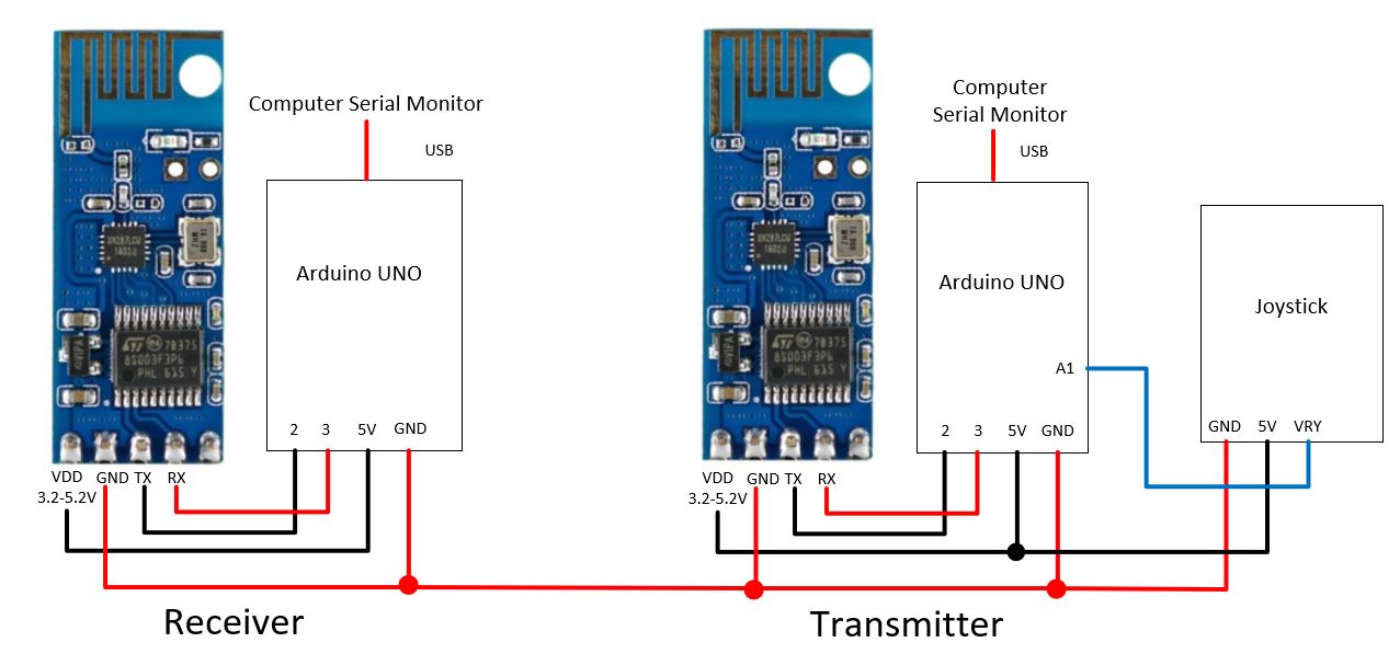
2. The Open-Smart 2.4 GHz transceiver (30 points)
Before connecting any wireless module to a circuit, you need to know
how data is being sent and received. Usually just send a number over
and look at them at the serial monitor.
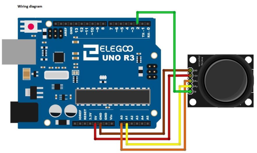
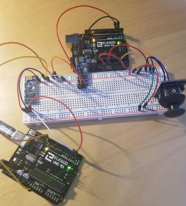
Make the following connections:
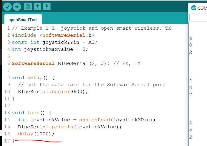
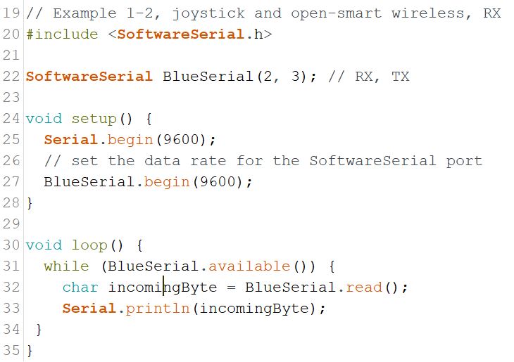
Here is the sketch for
the transmitter and the receiver. Upload them separately to these two
UNO boards. (openSmartTest.ino)
At the transmitter end, add a delay to the end of each transmission so
it is not keep sending data to the receiver all the time. If I let the
joystick rest, it sends 482 to the receiver. It is about half of 1023,
which is the full range of the 10-bit ADC.
You may have noticed that the numbers being received are different from
the numbers in Section 1. It sends one number each time and creates a
new line "\n" when all the numbers are sent. In Section 1, there is no
involvement of the wireless module, the UNO board digitizes the analog
input and direct sends everything to the serial monitor.
In this example, the digitized data is sent to the wireless module
through a Soft Serial port, it separates the three digits and send one
at each time in the format of Character.
These characters need to be converted into numbers to drive the motor
driver. Also, they need to be reformatted and combined into one number
for each joystick reading.
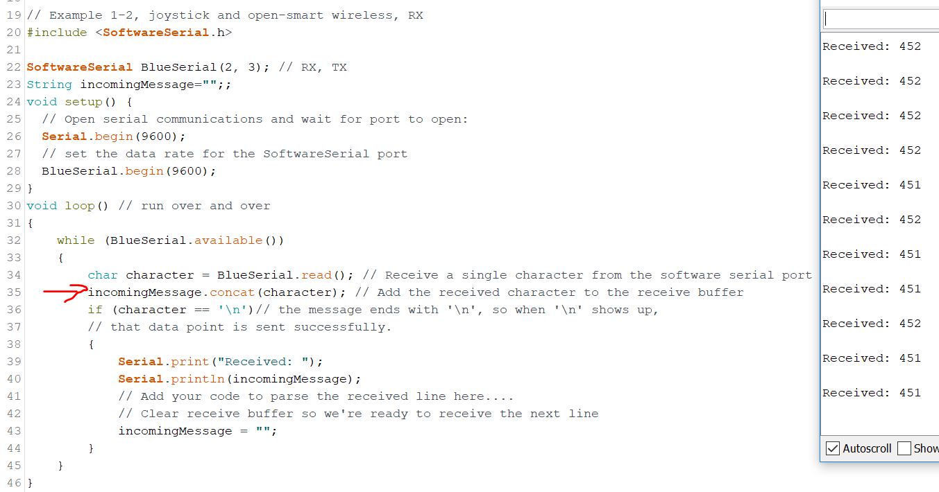
When you modify the code on the receiver end, you can detect the new
line '\n' as the delimiter of different data points. The numbers for a
data points can be set as characters and combined into a string.
3. Use the received command to control
the NEMA17 stepper motor (30 points).
Follow the instruction
in this link to connect the A4988 driver and the stepper motor to
the existing circuit.
Since Pin 2 and 3 are occupied by the SoftSerial ports, I used Pin 4 and 5 for Step and Dir respectfully. Here is the first sketch to just show the joystick works for the motor (openSmartTest3).
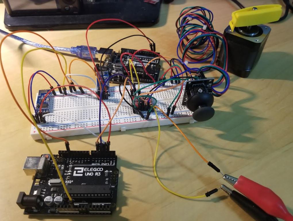
Here is the circuit connections on a breadboard:
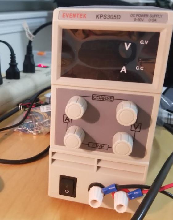
I used a benchtop DC power supply. You can use a 3-cell lipo battery. I
have plenty of these batteries and cartridges, please request these
materials from me.