The 1-core CPU of the Arduino
Board is expected to operate at two modes
at the same time - receive the data from the MPU board through I2C and
manage the PID controller. Both of the two tasks are being exeuted in
realtime so the only way to manage this is using an interrupt.
The strategy here is to
trigger the interrupt service routine (ISR)
every 20 us to deliver the PID results at THAT moment to the stepper
motors. Compare to the mechanical movement of the motor, the 20 us
activation is nothing so it will be able to adjust the movement
accordingly and smoothly.
Use the following code to set
up the ISR in your setup() function:
TWBR =
12;
//Set the I2C clock speed to 400kHz. TWSR is 8'b0 by default
//To create a variable pulse for controlling the stepper motors a timer
is created that will execute a piece of code (subroutine) every 20us
//This subroutine is called TIMER2_COMPA_vect
TCCR2A =
0;
//Make sure that the TCCR2A register is set to zero
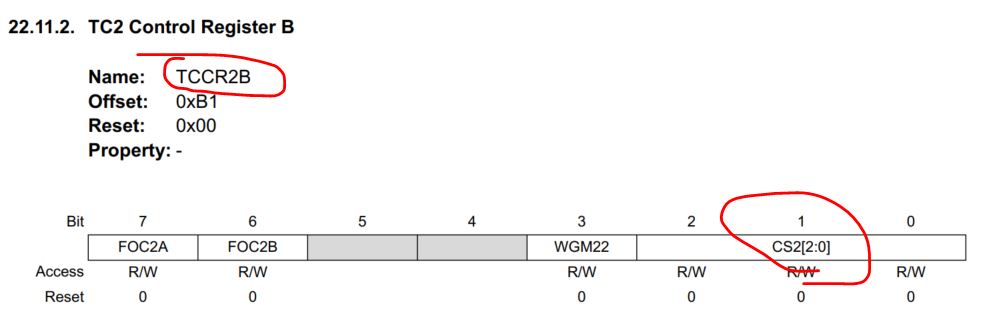
TCCR2B =
0;
//Make sure that the TCCR2B register is set to zero
TIMSK2 |= (1 <<
OCIE2A);
//Set the interupt enable bit OCIE2A in the TIMSK2 register
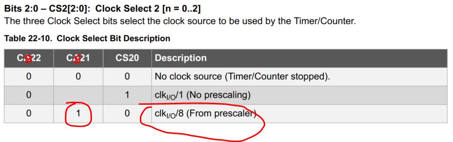
TCCR2B |= (1 <<
CS21);
//Set the CS21 bit in the TCCRB register to set the prescaler to 8
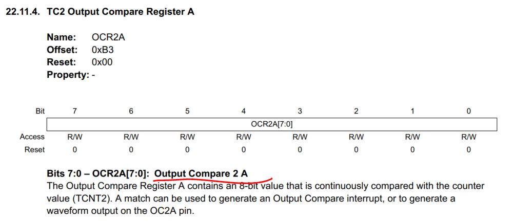
OCR2A =
39;
//The compare register is set to 39 => 20us / (1s / (16.000.000MHz /
8)) - 1
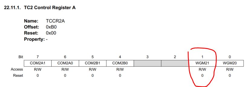
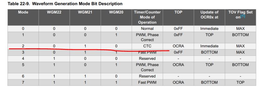
TCCR2A |= (1 <<
WGM21);
//Set counter 2 to CTC (clear timer on compare) mode
Now let's take a look at the
function of the registers in the datasheet.
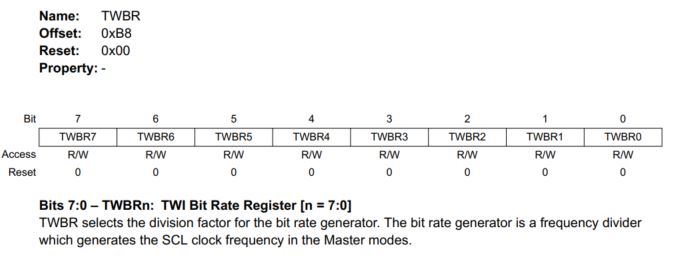
On Page 292, the TWBR register
is explained:
The 328p is being driven by a
16 MHz crystal, if the factor is set at
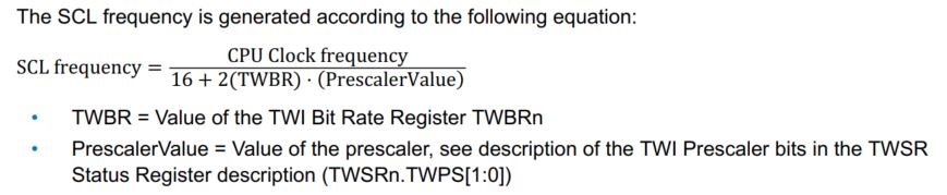
12. The equation to calculate the bit rate is on Page 267:
The CPU clock frequency is 16M Hz, TWBR=12, PrescalerValue = 1. The
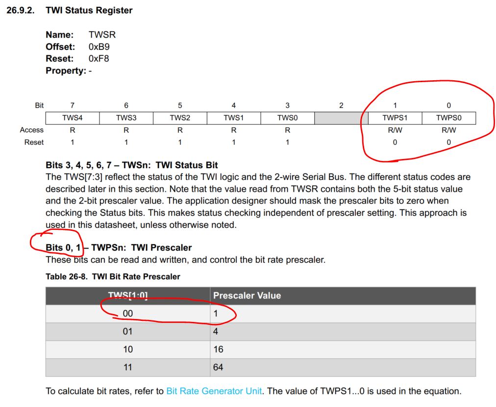
PrescalerValue is determined by the TWSR register, on Page 293:
The default values are 00 for bit 1:0, so the corresponding
PrescalerValue is 1.
So the bit rate for the I2C communication (SCL) is 16M/(16+2x12)=400
kHz.
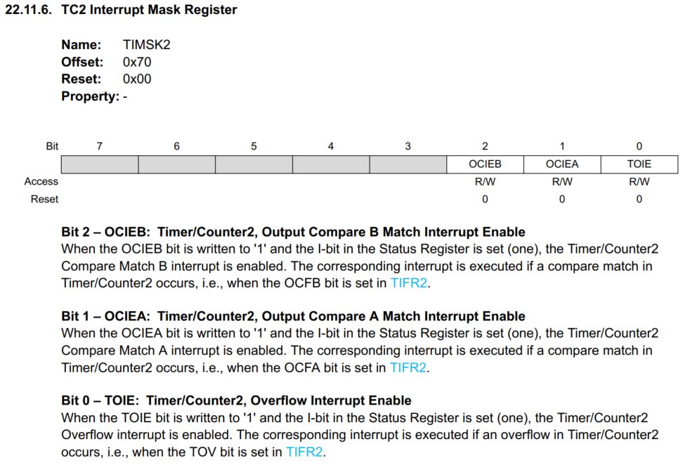
The TIMSK2 register:
As the OCIEA (or OCIE2A) is set to 1, the Compare Match A Interrupt
mode is enabled.
The TCCR2B register, set the prescaler to 8:
Set the OCR2A register, which
stores the number to compare, to 39:
In that case, the ISR will be
triggered for every 16M/8
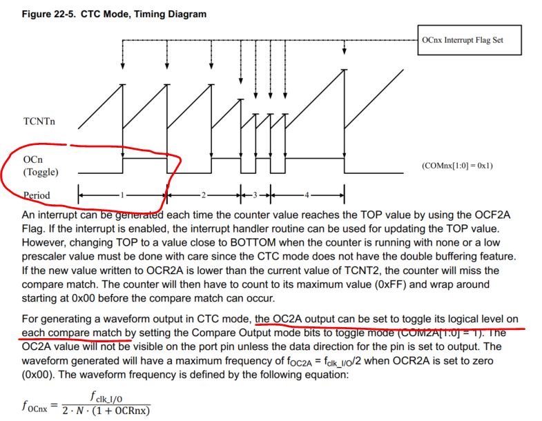
Toggle on each match:
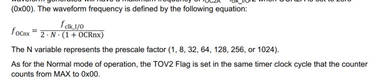
Which means every 20 us it
toggles and trigger the ISR, so the period
is actually 40 us, so the equation becomes:
1/40us = 16M/(2x8x(1+x)), and
x = 39
Finally, set it at the CTC
mode:
2. The demonstration sketch to get you
started
The following sketch contains the entire 'loop()' function that limits
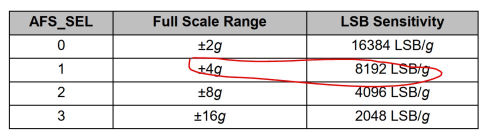
the accelerometer data within the -8192 and 8192 range. The 8192 was
predefined as explained in the previous tutorial: The binary value occasionally
overflows and goes above 8192 slightly. Use a IF Statement to limit it
within the range.
Read the following sketch.
You can use it for your first test. It can be directly used as the
loop() function of the your sketch. It'll let the car stand still. (Only shows the loop and ISR)
void
loop(){
Wire.beginTransmission(MPU);
//Start communication with the gyro
Wire.write(0x3F);
//Start reading at register 3F
Wire.endTransmission();
//End the transmission
Wire.requestFrom(MPU,
2);
//Request 2 bytes from the gyro
accelerometer_data_raw =
Wire.read()<<8|Wire.read();
//Combine the two bytes to make one integer
accelerometer_data_raw +=
acc_calibration_value;
//Add the accelerometer calibration value
if(accelerometer_data_raw > 8192)accelerometer_data_raw =
8192;
//Limiting the acc data to +/-8192;
if(accelerometer_data_raw < -8192)accelerometer_data_raw = -8192; angle_acc =
asin((float)accelerometer_data_raw/8192.0)* 57.296;
//Calculate the current angle according to the accelerometer
Wire.beginTransmission(MPU);
//Start communication with the gyro
Wire.write(0x45);
//Start reading at register 45
Wire.endTransmission();
//End the transmission
Wire.requestFrom(MPU,
2);
//Request 2 bytes from the gyro
gyro_pitch_data_raw =
Wire.read()<<8|Wire.read();
//Combine the two bytes to make one integer
gyro_pitch_data_raw -=
gyro_pitch_calibration_value;
//Add the gyro calibration value angle_gyro
+= gyro_pitch_data_raw *
0.000031;
//Calculate the traveled during this loop angle and add this to the
angle_gyro variable
angle_gyro = angle_gyro * 0.9996 + angle_acc *
0.0004;
//Correct the drift of the gyro angle with the accelerometer angle
pid_error_temp =
angle_gyro-0;
//Find the error between the current angle and 0
pid_i_mem += pid_i_gain *
pid_error_temp;
//Calculate the I-controller value and add it to the pid_i_mem variable
if(pid_i_mem > 400)pid_i_mem =
400;
//Limit the I-controller to the maximum controller output
else if(pid_i_mem < -400)pid_i_mem = -400;
//Calculate the PID output value
pid_output = pid_p_gain * pid_error_temp + pid_i_mem + pid_d_gain *
(pid_error_temp - pid_last_d_error);
if(pid_output > 400)pid_output =
400;
//Limit the PI-controller to the maximum controller output
else if(pid_output < -400)pid_output = -400;
pid_last_d_error =
pid_error_temp;
//Store the error for the next loop
if(pid_output < 5 && pid_output > -5)pid_output =
0;
//Create a dead-band to stop the motors when the robot is balanced
if(pid_output==0){ // if the car is balanced, do not output any power
to the motor
delayToBeAdded=0; // if
delayToBeAdded is 0, in the ISR, it will never trigger the motor. }
else {
delayToBeAdded = 5500/(abs(pid_output) + 9); // to
linearize the output }
//The angle calculations are tuned for a loop time of 4 milliseconds.
To make sure every loop is exactly 4 milliseconds a wait loop
//is created by setting the loop_timer variable to +4000 microseconds
every loop.
while(loop_timer > micros()); // while loop_timer > micros(),
hold there and wait
loop_timer +=
4000; //
once loop_timer < micros(), add 4000 us to loop_timer. }
The ISR function will be invoked every 20 us. Every time it enters it, the counter_motor
variable will increase by 1, then it is immediately compared to the
'delayToBeAdded' variable. If 'delaytoBeAdded' is large (a small
pid_out value), it takes many 20 us cycles to satisfy the condition of
the IF Satement, then clear the counter_motor variable. Otherwise, the
ISR will basically do nothing except for the increment of counter_motor
variable.
After counter_motor is reset
to 0 in ISR, the 'else if' conditions will be satisfied the next time
it enters the ISR and add a step to the wheels.
ISR(TIMER2_COMPA_vect){
counter_motor ++; if
(counter_motor > delayToBeAdded){ // this if statement block only defines the direction of the two motors.
counter_motor=0;
if (pid_output>0){
PORTD &= 0b00000000; //0b00DSDS00 (D: Dir, S: Step), reset all bits for Port D is just preparing for the line below it. '0b' is to represent binary numbers. '0x' is for Hex numbers.
PORTD |= 0b00001000; //Two different directions for the two steppers on two sides. (the car leans forward)
}
else {
PORTD &= 0b00000000;
PORTD |= 0b00100000; // Two different directions for the two steppers on two sides. (the car leans backward)
} } // The following lines will provide a step to the stepper motor
else if(counter_motor == 1) PORTD |=
0b00010100;
//Set output 2 high and low to create a pulse for the stepper controller.
else if(counter_motor == 2) PORTD &=
0b11101011; }
This is the end of this
tutorial. The tasks for you is to refer to the tutorial of the YABR
website and build a wirelessly controlled 2-wheel balanced car. You can
choose to use your smartphone or a joystick to control it. Make a PCB
and a 3D printing case for you product.
CE 432 Robotics II Course Project (40% of the overall grade)
Task 1: Complete the simplified version of the project shown in the
video demonstrastion above. (video demonstration required) (40 points)
The car should be balanced on a flat surface.
Place a waterbottle on the top of the car it should still be balanced.
Push the car forward and backward, the car moves and balanced.
(extra credit)
Task 2: Add the joystick to the system. The car should be able to move
forward, backward, turn left and right under the control of the remote.
(extra credit)
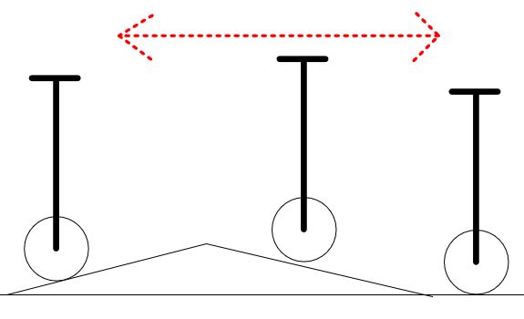
Task 3: Pass the ramp test in two directions. (start with a small angle, for example, 10 degree).
Task 4: PCB design, fabrication, soldering, and testing. Two boards,
one for the remote, one for the car. (team work) (40 points)
Task 5: Final testing, presentation, and report writing. (team work) (20 points)