The datasheet can be
downloaded here,
The Torque Curve can be downloaded here.
Watch: How a stepper motor works?
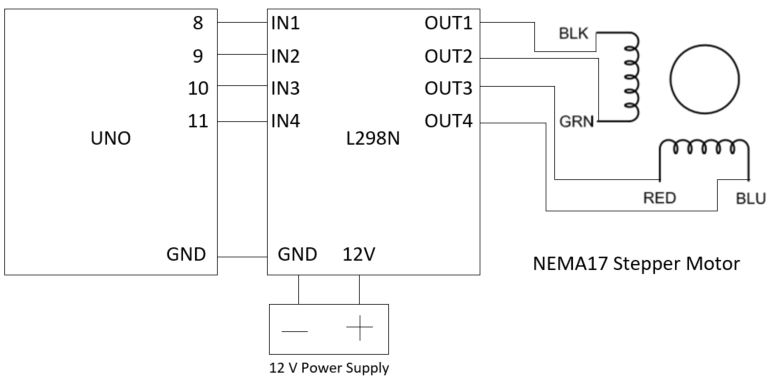
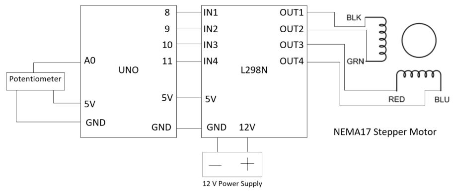
1. Basics 1.1. Drive
the motor using the L298N
H-Bridge driver
The first step is to use the
basic circuit and code to test drive the
stepper motor. What you need: 1. A power supply can provide
12 V DC and 2 A as the minimum. 2. A NEMA17 stepper motor 3. One Arduino UNO board 4. An L298N stepper motor
driver module 5. A breadboard and jumping
wires.
To make the following
connection:
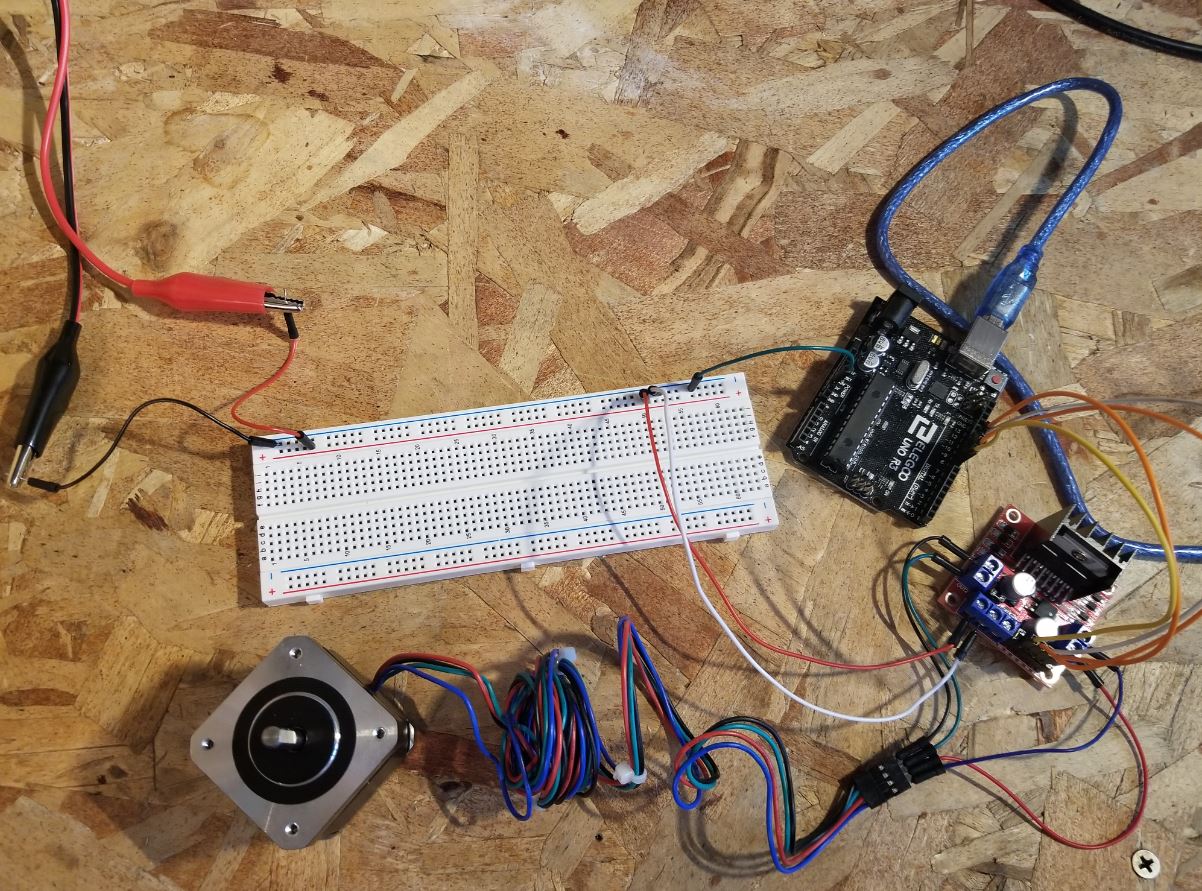
The real circuit looks like
this:
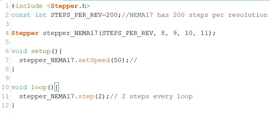
The Arduino code to kick if
off:
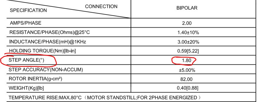
In NEMA17's datasheet, the
STEP ANGLE parameter tells you the 'steps
per revolution' you have to define in your sketch. Every step moves 1.8
degree, there are 360 degrees per revolution so totally 200 steps.
The demonstration video:
Task
1: Repeat the work
demonstrated in the video. (CE432 students, please skip Task 1 in this tutorial)
1.2 Use a
potentiometer to change the
speed in realtime
You can use a potentiometer
to control the RPM of the stepper motor. Make the following
connections:
Task
2: Repeat the work
demonstrated in the video. (CE432 students, please skip Task 2 in this tutorial)
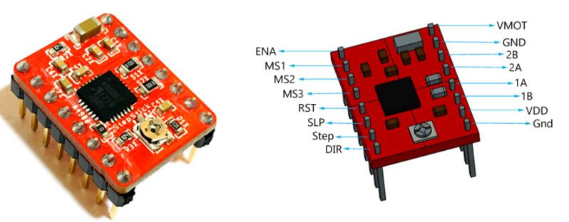
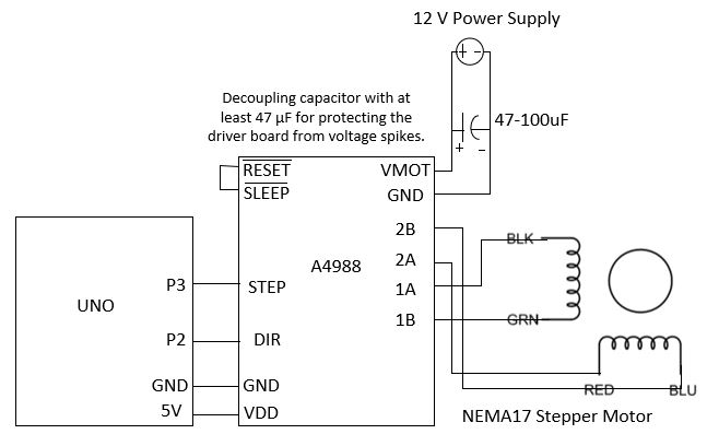
1.3 Use
the A4988 stepper motor driver
A4988 is an alternative
product to the L298N driver.
The A4988 is a microstepping
driver for controlling bipolar stepper
motors which has built-in translator for easy operation. This means
that we can control the stepper motor with just 2 pins from our
controller, or one for controlling the rotation direction and the other
for controlling the steps.
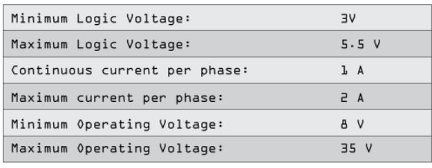
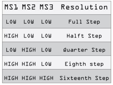
The Driver provides five
different step resolutions: full-step,
haft-step, quarter-step, eight-step and sixteenth-step. Also, it has a
potentiometer for adjusting the current output, over-temperature
thermal shutdown and crossover-current protection. Its logic voltage is
from 3 to 5.5 V and the maximum current per phase is 2A if good
addition cooling is provided or 1A continuous current per phase without
heat sink or cooling.
The next two 2 pins, Step and
Direction are the pins that we actually
use for controlling the motor movements. The Direction pin controls the
rotation direction of the motor and we need to connect it to one of the
digital pins on our microcontroller. With the Step pin we control
the mirosteps of the motor and with each
pulse sent to this pin the motor moves one step. So that means that we
don’t need any complex programming, phase sequence tables, frequency
control lines and so on, because the built-in translator of the A4988
Driver takes care of everything. Here we also need to mention that
these 2 pins are not pulled to any voltage internally, so we should not
leave them floating in our program.
Next is the SLEEP Pin and a
logic low puts the board in sleep mode for
minimizing power consumption when the motor is not in use. Next, the
RESET pin sets the translator to a predefined Home state. This Home
state or Home Microstep Position can be seen from these Figures from
the A4988 Datasheet. So these are the initial positions from where the
motor starts and they are different depending on the microstep
resolution. If the input state to this pin is a logic low all the STEP
inputs will be ignored. The Reset pin is a floating pin so if we don’t
have intention of controlling it with in our program we need to connect
it to the SLEEP pin in order to bring it high and enable the board.
The next 3 pins (MS1, MS2 and
MS3) are for selecting one of the five
step resolutions according to the above truth table. These pins have
internal pull-down resistors so if we leave them disconnected, the
board will operate in full step mode. The last one, the ENABLE pin is
used for turning on or off the FET outputs. So a logic high will keep
the outputs disabled.
Datasheet of the A4988 driver
IC can be downloaded here.
The module's pinout and specs can be
found here.
Some notes:
- Every pulse will create one step, which is 1.8 degree (if it is a fll
step, MS1 MS2 MS3 is 0 0 0), the pulse width cannot be too small.
The example uses 500 us as the pulse width and it works fine. I tried
400 us and it doesn't work. You can also use wider pulses, say 1000 us,
the rotation speed will be slower.
- 7.4 V for VMOT also works which means you can use a 2-cell lipo battery.
- The 47 - 100 uF cap shorting VMOT to GND can be absent without
causing anything, but it is highly recommended to have it in place.
Task
3: Repeat the work
demonstrated in the video. (CE432 students, please skip Task 3 in this tutorial)
1.4 Use
the A4988 driver and a
potentiometer to adjust the motor speed in realtime.
Follow the instructions in
section 1.2 and try to repeat the same
results using the A4988 driver.
The demonstration video:
Task
4: Repeat the work
demonstrated in the video. (CE432 students, please skip Task 4 in this tutorial)
2. Test
the MPU6050 accelerometer/gyroscope sensor 2.1
Understand acceleration and angular velocity
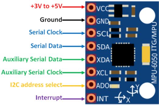
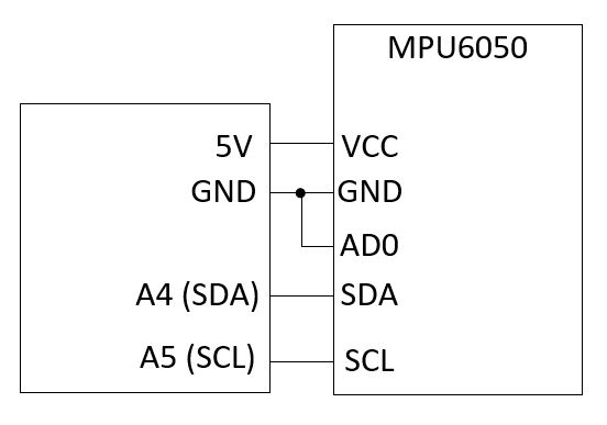
The pinout of MPU-6050
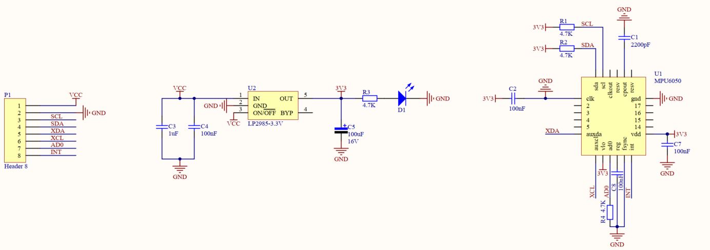
The schematic of the module:
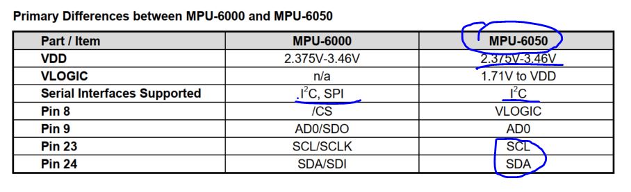
Table of voltage ratings:
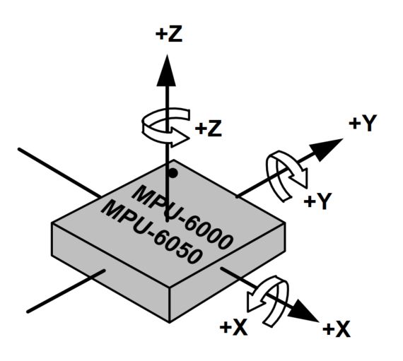
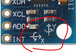
MPU-6050 Axis:
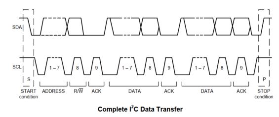
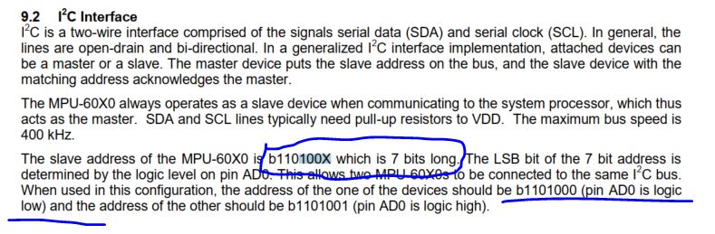
MPU I2C communication:
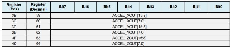
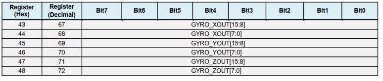
The key registers:
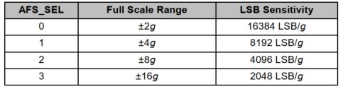
Binary readout data / LSB Sensitivity = xxx LSB / (LSB / g) = xxx g.
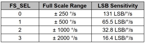
Binary readout data / LSB
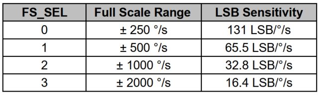
Sensitivity = xxx LSB / (LSB / (deg/s)) = xxx deg/s. This is the
angular velocity but how do you get the rotated angles in realtime? -
You must know the time spent for each 'void loop ()' function.
Use the following software
and hardware to test your accelerometer and gyroscope before it's being
connected to the car.
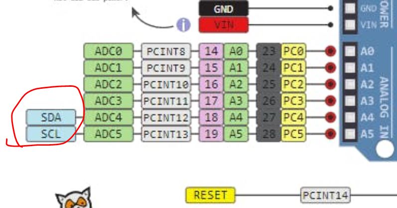
From the UNO's
pinout, you can idenfy
the I2C pins are A4 and A5:
Make the following hardware
connections:
Use this
example to test your
acceleration and gyroscope readings respectively. Check out MPU6050's datasheet and register
map if you have questions
about the example sketch.
By holding the MPU6050 sensor
at different gestures, you
can understand what the accelerometer and the gyroscope are measuring.
The
Gyro measures angular velocity. Therea are three axes X, Y, and Z, the
direction of them are indicated on the module's PCB board.
The Z axis in the snippet
above points out of your monitor and perpendicular to the PCB board.
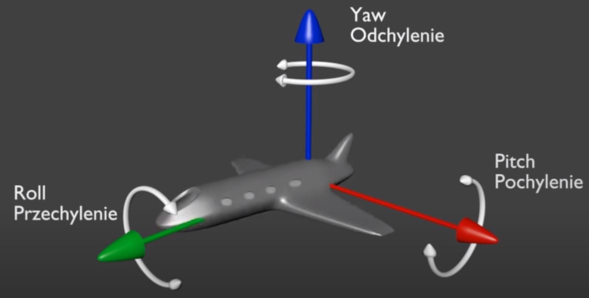
Let's take the airplane's X, Y, and Z axes as the example.
For airplane control, Pitch, Roll and Yaw are defined as the
rotation around X, Y and Z axis. Below as a picture to illustrate the
definition.
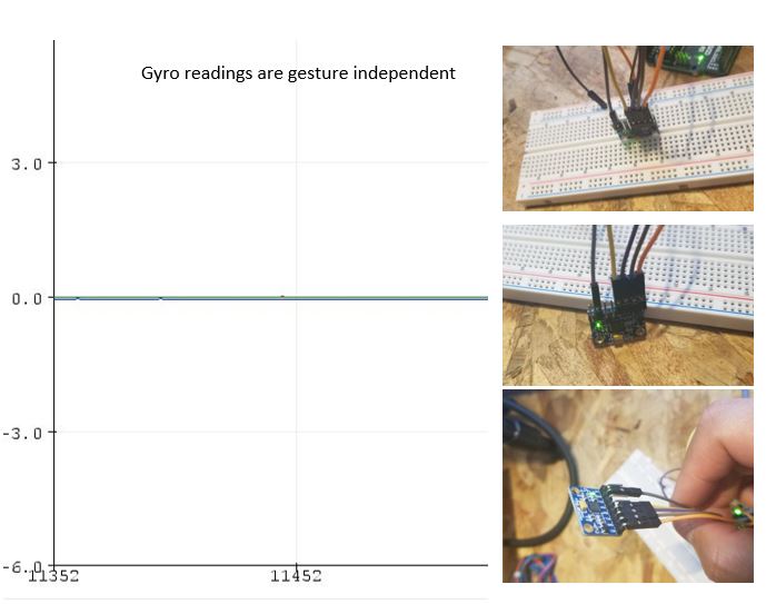
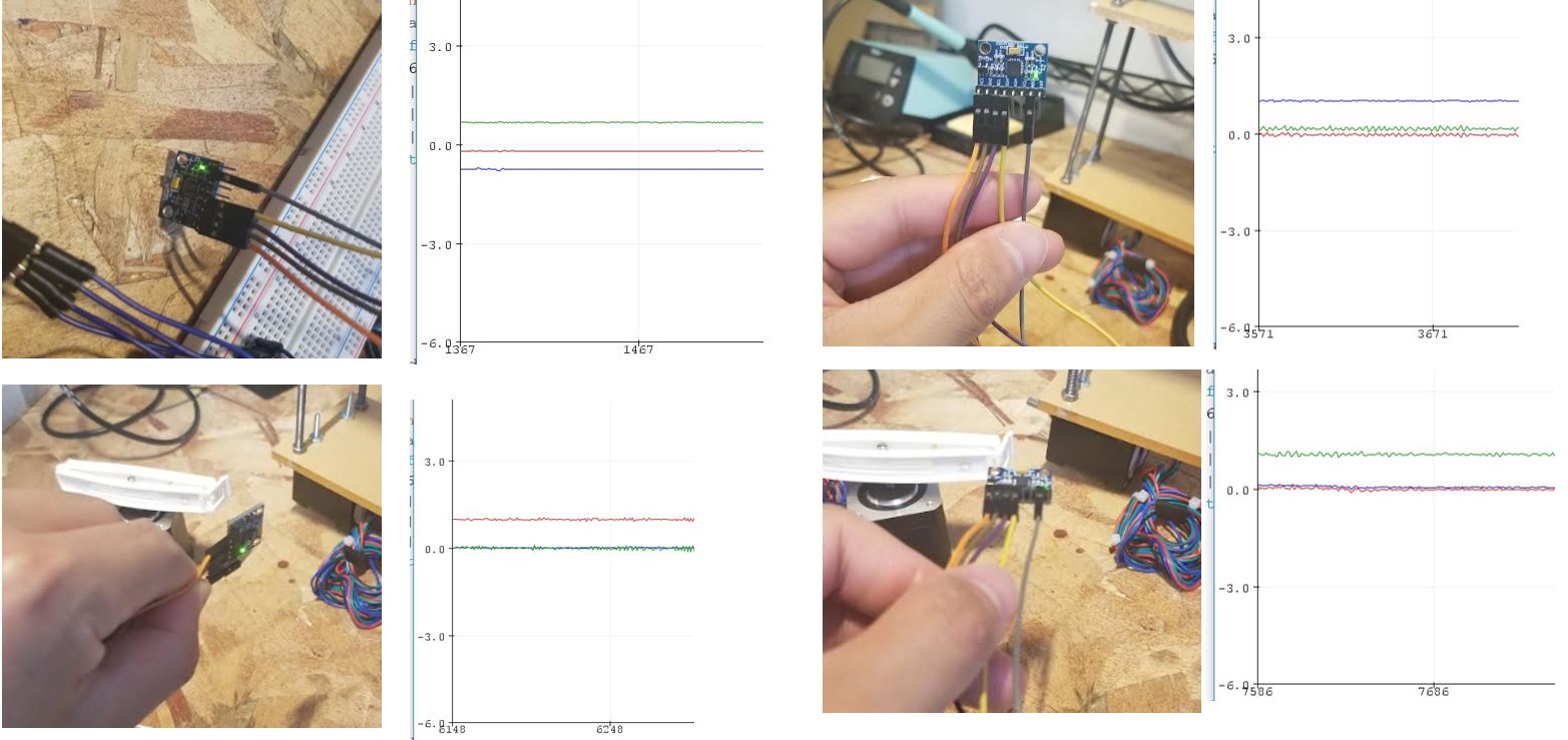
If the MPU is idle, no
movement and no rotation, the Gyro readout should be all zeros.
Look at the following
demonstration that I held the MPU module at different angles
statically, the readout is always zero.
However, the acceleration
readout values reacts to the angular changes. (I have converted the unit of the readings to
'g' for the following tests).
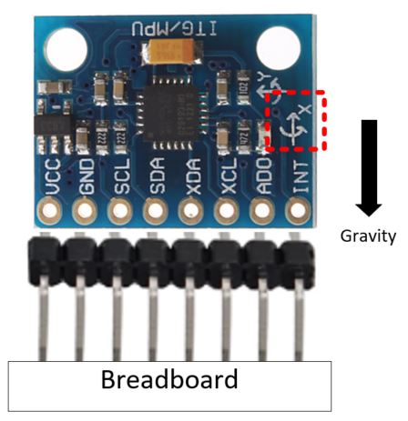
Keep
in mind that gravity always exists so if you plug your MPU
module on a breadboard vertically as follows:
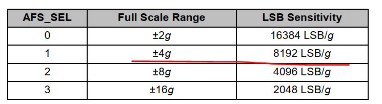
You are supposed to receive
something close to 8192 for Accel_X.
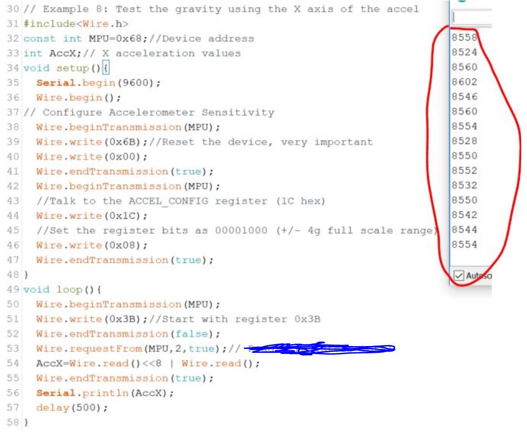
The number '8192' comes from the following
configuration according to the register map.
Task 5: Modify
the MPU's code I provided in the last section to display the raw
acceleration data of the X axis as shown in the following figure. The
MPU module is placed perpendicular to the board.
(All these 8500+ values are supposed to be 8192 but you can tell the
level of the deviations by holding it by hand and the system errors of
itself. The values are positive so
disregard the direction of the arrow printed on the MPU module for the
X axis. )
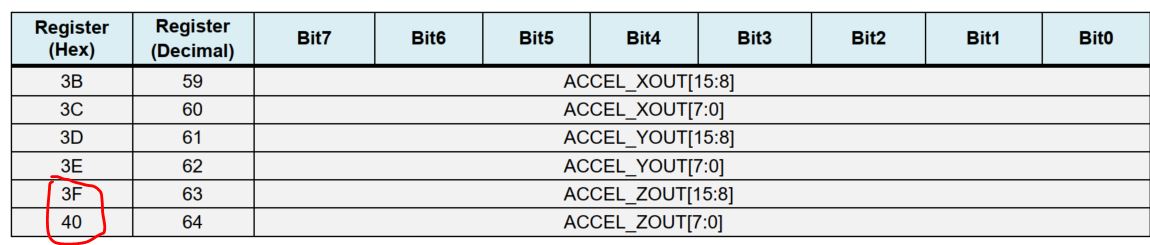
The code starts with the 0x3B register
for data reading because the 2-byte X axis data is stored in 0x3B
and 0x3C.
2.2 Remove
the offset of the Gyro's readings
In last section you may have
noticed that Gyro's readings are not perfectly 0:
You can add a calibration
section in your code to average out the first 500 readings to calibrate
the Gyro's reading. Here is the piece of the code
to peform the calculation.
for (receive_counter = 0; receive_counter < 500;
receive_counter++){ //Create 500
loops
if(receive_counter
% 15 == 0) digitalWrite(13,
!digitalRead(13)); //Change
the state of the LED every 15 loops to make the LED blink fast
Wire.beginTransmission(MPU);
//Start communication with the gyro
Wire.write(0x45);
//Gyro Y_OUT
Wire.endTransmission();
//End the transmission
Wire.requestFrom(MPU,
2);
//Request 2 bytes from the gyro
gyro_pitch_calibration_value +=
Wire.read()<<8|Wire.read();
//Combine the two bytes to make one integer
delayMicroseconds(3700);
//Wait for 3700 microseconds to simulate the main program loop time,
CRITICAL!! }
gyro_pitch_calibration_value /= 500; }
Task 6: Use the code above to report the
averaged 'gyro_pitch_calibration_value'
to your serial monitor (with 500 ms delays in between the readings).
2.3 The
loop_timer variable
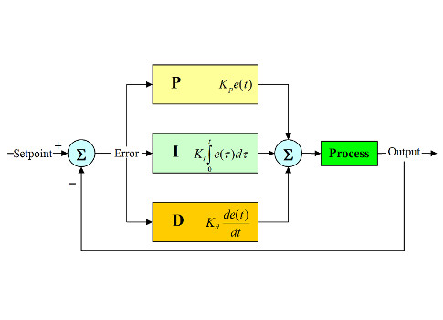
There is a time delay created
by the feedback loop of the PID
controller. In this experiment, the time delay is caused by the finite
oscillation frequency of the crystal and the time constants of the
entire circuit.
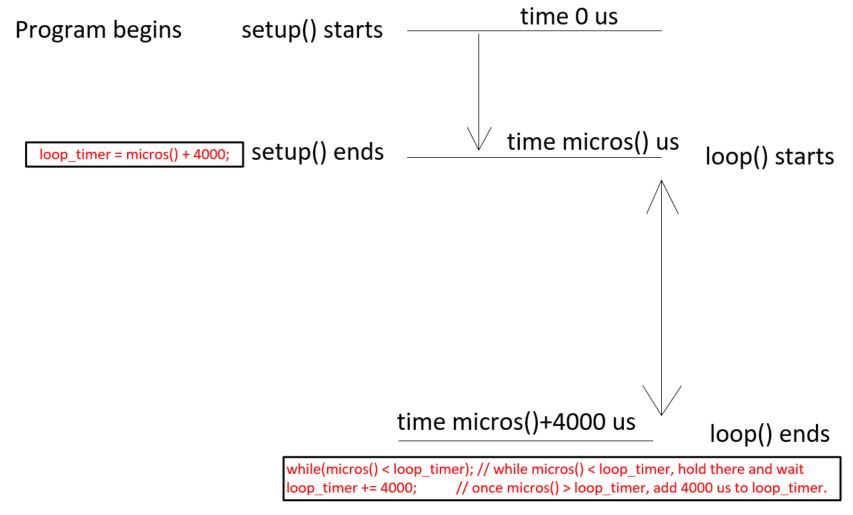
To unify the 'delta_t' of the PID controller of every loop of the
loop() fuction, you can start timing the loop time by adding the
following line in the end of the setup() function.
setup(){
.......................
.......................
loop_timer = micros() +
4000;
//Set the loop_timer variable at the next end loop time }
The micros()
function returns the number of microseconds since the Arduino board
began running the current program. This number will overflow (go back
to zero), after approximately 70 minutes. On 16 MHz Arduino boards
(e.g. Duemilanove and Nano), this function has a resolution of four
microseconds (i.e. the value returned is always a multiple of four).
This is to add the time spent
on the setup() function to 4000 us (4 ms). You need it to be added to
4000 us since 4000 us is the desired loop time (delta_t) for the PID
controller. Of course 4000 us is not the only value that you can use
here. This is value is identified by testing the time delay of evey
loop and picking up a value that is a little larger than that time.
Add micros() to 4000 is to
set the standard time delay of the loop() function to 4000 us. If the
loop() function spends less it should be manually delayed inside the
function until it uses all 4000 us. To do this, in the end of the
loop() function, add the following line:
loop(){
.......................
.......................
while(micros() < loop_timer); // while micros() < loop_timer,
hold there and wait
loop_timer +=
4000; //
once micros() > loop_timer, add 4000 us to loop_timer. }
The setup() function only
runs once, so the time spent on it is not counted in 'delta_t'.
Task 7: Use
this technique to blink an LED at 1 Hz (the program shouldn't have
anything irrelavent to the LED blinking program). Show the video
demonstration.
2.4 Angle
calculation
MPU is able to measure the
angles by combining the information from the accelerometer and the
gyroscope.
If the MPU module is inserted
to the breadboard perpendicularly, the direction of the three axes are
as follows: Z front/back, X is up/down, and Y is left/right:
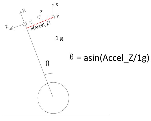
If the car leans forward, the
wheels should move forward to prevent it
from tipping over. If it leans backward, wheels should move backward. The vertical acceleration is
always 1 g, so the angle can be calcualted using the asin() fuction:
Theta = asin(Accel_Z/1g). The result of this equation
is in radians, to convert it to angles, you
need to multiply it by 180/pi (or 360/2pi), which is 57.296: Theta =
asin(Accel_Z/1g) x 57.296. To implement it in Arduino:
asin((float)accelerometer_data_raw/8192.0)*
57.296 // 8192
is the LSB/g configuration for the MPU chip
The Accel_Z value may have a
little offset when you hold your 2-wheel
balanced car up right. Mount the sensor to the car, test the Accel_Z
offset and substract it from the the Accel_Z readings every cycle. Mine Accel_Z offset is 450 so it was subtracted from the reading:
Declare it as follows:
int
acc_calibration_value = -450;
and subtract it in the loop()
function:
Wire.beginTransmission(MPU);
//Start communication with the gyro
Wire.write(0x3F);
//Start reading at register 3F
Wire.endTransmission();
//End the transmission
Wire.requestFrom(MPU,
2);
//Request 2 bytes from the gyro
accelerometer_data_raw =
Wire.read()<<8 |
Wire.read();
//Combine the two bytes to make one integer
accelerometer_data_raw +=
acc_calibration_value;
//Add the accelerometer calibration value
For Gyro's readout data is
angular velocity (degree/s), the loop time
is 4000 us, so the Gyro raw data should be converted in degrees using
the following formula:
Gyro Raw Data (delta angle change in LSB/degree/s) x 0.004 s /(131
LSB/degree/s) = Gyro Raw Data x 0.00031
The angle accumulates. All
new angles are results of displacement of
the original angles. The way to get he current angle is to keep track
all the previous angles but not just record the most recent
'delta_degree). To implement it in Arduino:
gyro_pitch_data_raw
-=
gyro_pitch_calibration_value;
//Subtract the gyro calibration value angle_gyro
+=
gyro_pitch_data_raw *
0.000031;
//Calculate the traveled angle during this loop angle and add this to
the angle_gyro variable
Now, the Data Fusion is a
very common technique to filter out the
high-frequency components and keep the low frequency components.
angle_gyro
= angle_gyro * 0.9996 +
angle_acc *
0.0004;
//Correct the drift of the gyro angle with the accelerometer angle
The angle_gyro variable
should store the real angle it has travelled.
We have two measurements of
the angle from two different sources. The measurement from accelerometer
gets affected by sudden horizontal movements and the measurement from
gyroscope gradually drifts away from actual value. In other words, the
accelerometer reading gets affected by short duration signals and the
gyroscope reading by long duration signals. These readings are, in a
way, complementary to each other. Combine them both using a Complementary Filter
and we get a stable, accurate measurement of the angle. The
complementary filter is essentially a high pass filter acting on the
gyroscope and a low pass filter acting on the accelerometer to filter out
the drift and noise from the measurement.
Task 8: Mount the MPU6050 sensor/breadboard on the top of the car. Gently lean the car from 0 degree
to 90 degree and -90 degree. Check if you are receiving 90 or -90 in the
serial monitor. Video demonstration required.
The end of this tutorial------------------------------------------------------------
Tasks for CE432 (f2021) students:
Part 1: Task 5-8: 20 points for each. Part 2: Use only the accelerometer's
data to calculate the angles and repeat Task 8 using the new sketch (20
points). Video demonstrastion required.