1. Get
started with the 28BYJ-48 stepper motor A stepper motor, also known
as step motor or stepping motor, is a brushless DC electric motor that
divides a full rotation into a number of equal steps. The motor's
position can then be commanded to move and hold at one of these steps
without any position sensor for feedback (an open-loop controller), as
long as the motor is carefully sized to the application in respect to
torque and speed.
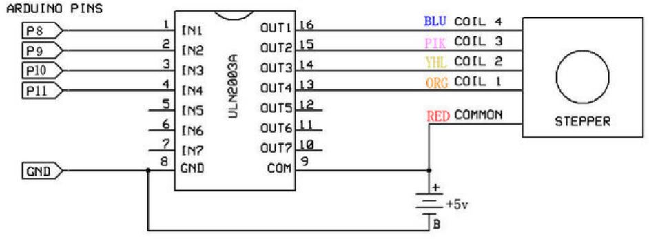
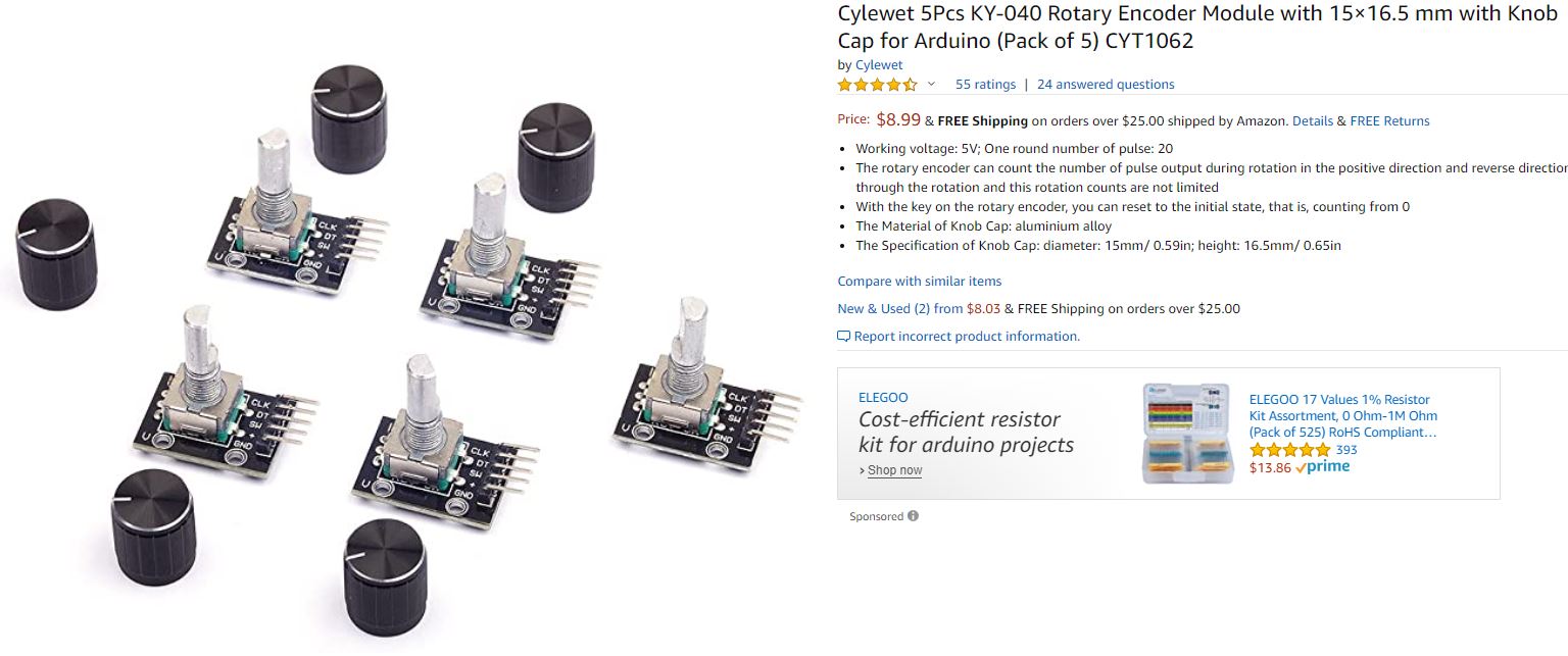
One round number of pulse: 20
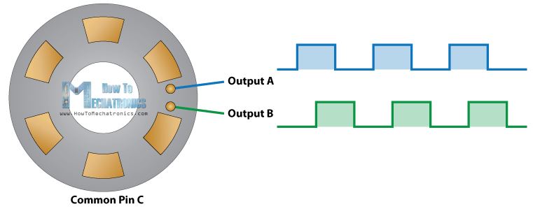
Working voltage: 5V The rotary encoder
can count the number of pulse output during rotation in the positive
direction and reverse direction through the rotation and this rotation
counts are not limited. With the key on the rotary encoder, you can
reset to the initial state, that is, counting from 0. The Material of
Knob Cap: aluminium alloy The Specification of Knob Cap: diameter:
15mm/ 0.59in; height: 16.5mm/ 0.65in.
Before start working with the encoder and the Arduino board, read this
tutorial first.
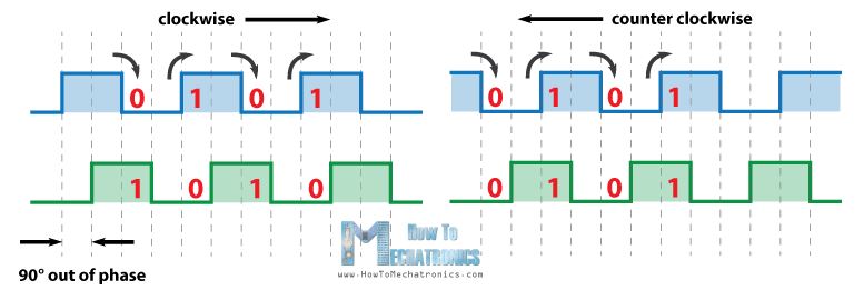
When the detectors A or B are on the top of the block, it outputs logic
HIGH pulses, otherwise it outputs LOW. If the rotor moves clock-wise,
then before A changes its state (from low to high or from high to low),
A and B are in the same state. If it rotates counter clock-wise, right
before A changes its state, A and B are in different states. We can use
this simple algorithm to code up a scirpt in Arduino to tell the
direction the rotor rotates.
Rotary
Encoder Arduino Example:
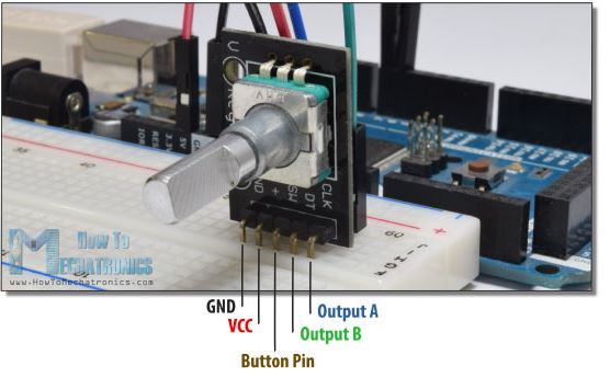
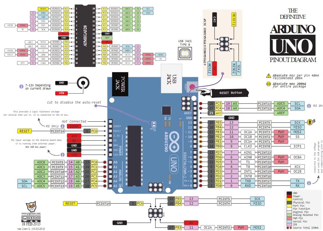
Make the following hardware connections:
Output A - Pin 6 (Arduino)
Output B - Pin 7 (Arduino)
Button Pin - Null (Keep it float for the first example)
VCC - 5V (Arduino)
GND - GND (Arduino)
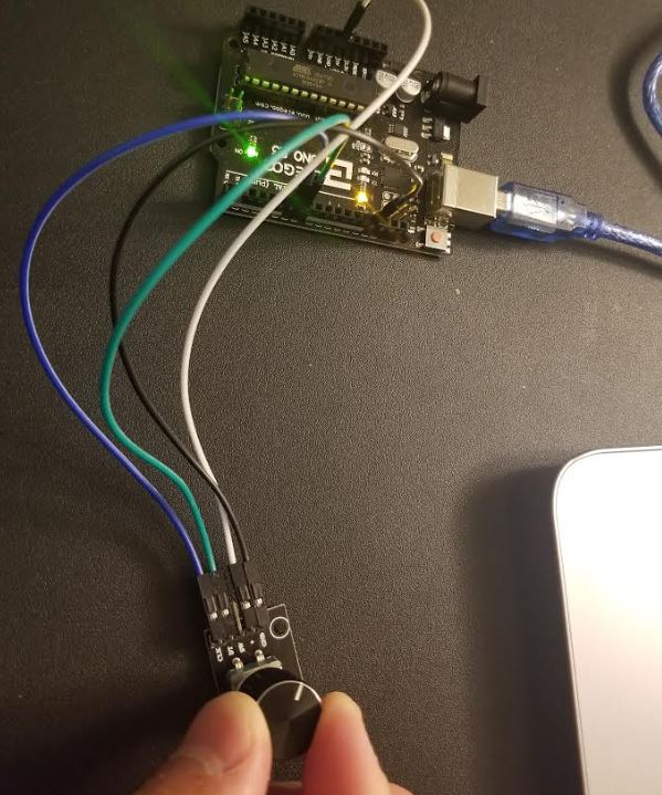
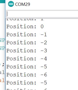
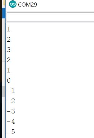
Load
the code to your Arduino
board. Open the Serial Monitor to check the positions of the encoder.
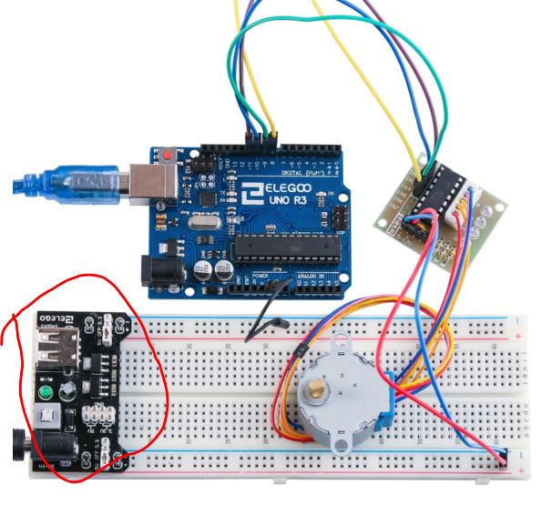
Now, let's add the stepper motor back to the breadboard and use the
encoder to control the movement of the stepper motor precisely.
The code is not provided here but you should be able to make your own
based on the code provided in the first two examples.
3. One Arduino UNO controls three 28BYJ-48
stepper
motors
Make the following
hardware connections and modify the code to use one
Arduino UNO board to control three stepper motors. (the code I made is
not
provided). You don't have to make it move in the same manner in the
demo video below but you must show the three stepper motores are being
controlled by one UNO board.
Keep in mind that, each step motor has a 1A current rating, the adapter
comes with the DCDC module you have has only 600 mA as a maximum. You
may use one of it to temporarily control ONE stepper motor but
definitely
not THREE !! It will heat up quickly and melt your
breadboard.
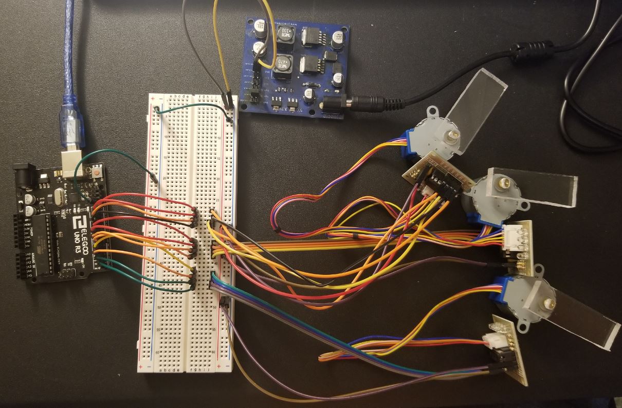
I explained the connections in between all of the parts in the figure
above in the following video:
Now, modify the code to make
three stepper motors rotate at the same
time with the same speed and direction.
Modify the code again to make
them rotate in different directions and
speed.
4. Use one
encoder to control one stepper motor.
Given that one Arduino baord
cannot do both motor control (three of them) and encoder control (three
of them). We will use one Arduino board dedicated for encoder data
collectiona and another Arduino board for motor control.
First, we need to select a
proper communication methanism betwee the two Arduino boards. I2C can
be a good option.
Use the this code for the master and the slave
respectively. Pay attention to the data
type being used in the slave. Since I2C sends bytes one by one,
You should see the encoder's
data is being sent to the slave Arduino through the master.
5. One stepper motor replicates the encoder's movements
Before we can make a robot arm that replicates the movements of three
encoders, we need to make one set work.
The idea here is to use two Arduino UNO boards, one records the
encoder's command (the master) and sends it to the other UNO board. The
other UNO board (slave) receives the commands and uses it to actuate
the stepper.
The communication between the two UNO boards we used here is I2C. You
can definitely use SPI or a software UART but not the hardware UART.
The reason is we rely on the hardware UART to provide debugging signals
to the serial monitor so we can visualize what just happened in the
system. If you use the hardware UART for the two UNO boards, the
traffic on the UART bus will be too much to make it correct.
Before moving forward, watch the video below and be clear with the goal
of this experiment. (The negative movements of
the encoders can be prevented by adding delays in the code. The
previous examples worked well because the Serial.println() function
takes the time delay in the code. If you don't have a print function,
adding 10ms delays will solve the problem. Add the 10 ms delay after
every state checking and try it again).
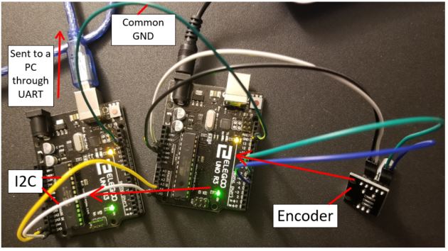
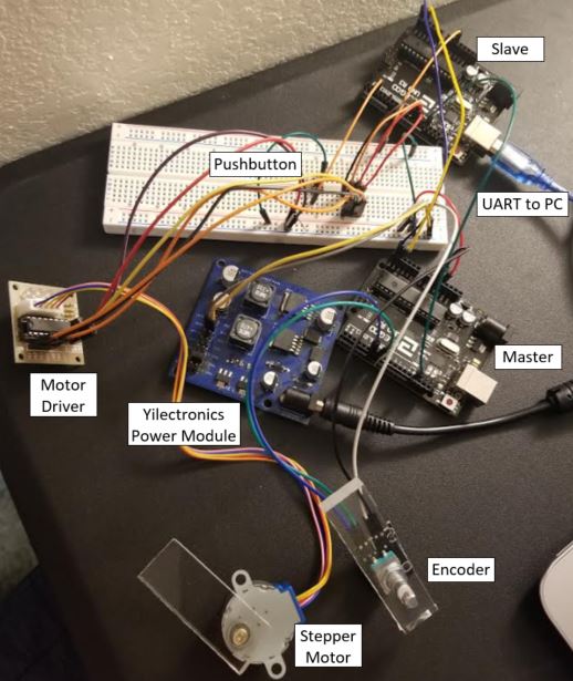
Now, let's start building it.
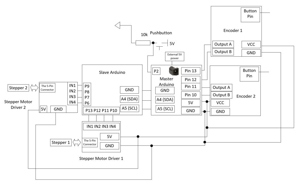
Well, the connections look messy:
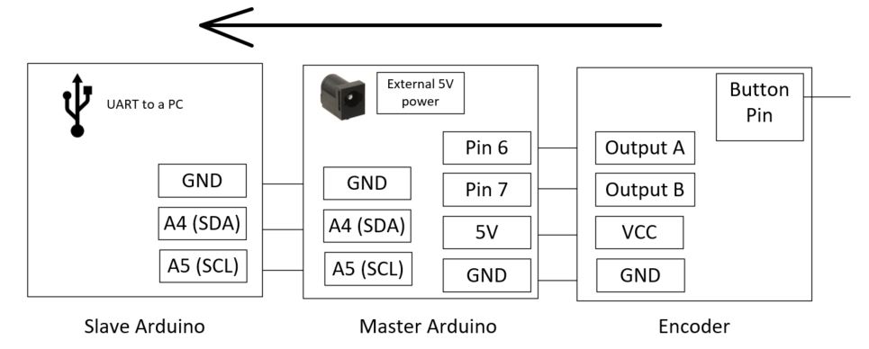
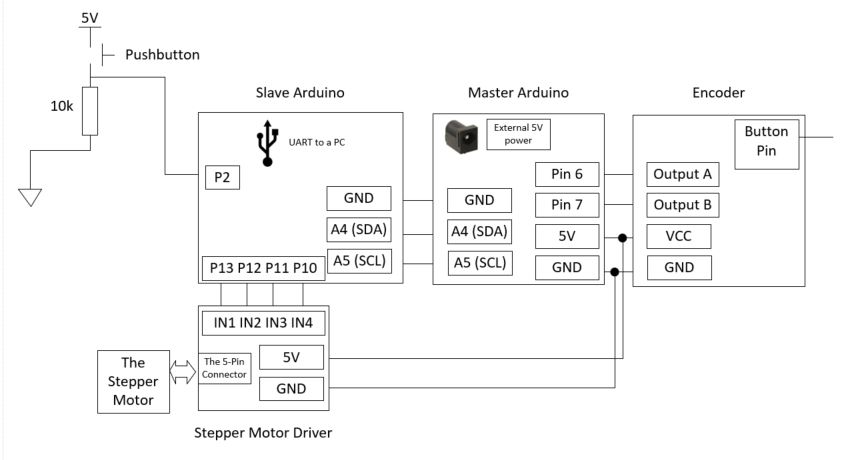
Here is the connection's diagram:
This following piece of code can be used for the pushbutton detection
at Pin 2:
----------------------------------------------------------- The tasks in the following section are not required for CE432 students in Fall 2020 6. Two
encoders and two stepper motors
The purpose of this section is to develop a 2-joint robotic arm that
can replicate the movement of the 2-joint encoder arm in a certain
sequence.
The Encoder arm is called the 'replica' here. It allows the user to
create a series of movement using the replica. The encoders record the
directions, magnitude, and sequence of the two joints and save them in
an integer array. A push button is used to send the data in the integer
array to the slave MCU and actuate the stepper motors accordingly.
When there are two motors moving at the same time, you must consider
the SEQUENCE of the movements. Yes, if you don't, the motors will still
move to the final destination finally, but the two motors will not
exactly replicate the moving trajectory and the sequence as the replica
just did.
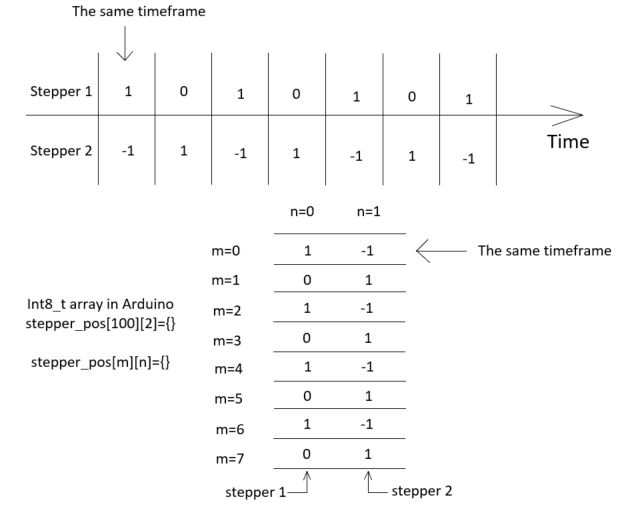
The way to solve this problem here is the divide the movement into
certian timeframes. The timeframes are short and the digital clock is
fast enough to pick up all the moves of the encoder.
There are 40 steps for ONE revolution for the encoder and 2038 steps
for ONE revolution for the stepper. We can roughly use 1 VS 50 to
mirror the moves of the enoder to the moves of the stepper, so one
encoder move will cause 50 stepper moves.
The way to construct the array to store the movements in different
timeframes:
The hardware connections:
The software won't be provided for this section. The demonstration
video can be found here:
(The 10 ms time delays are
added to the Encoder state checking cycles so the shakes are
prevented).
Tasks: Repeat the work in Section 1 - 5. (20 points for each)